
The neutral conductor is not inherently smaller than the phase conductors. In a balanced three-phase linear load, fundamental-frequency phase currents cancel at the neutral point. In an installation supplying nonlinear single-phase loads, triplen harmonic currents can instead add in the neutral—even when the phases are well balanced.
Neutral conductor sizing therefore begins with the expected neutral current spectrum and installation thermal conditions, followed by the applicable wiring and protection rules. A balanced load schedule alone does not justify reducing the neutral area. This article concerns a separate load neutral in a three-phase four-wire circuit, not a combined protective-and-neutral conductor or an earthing-system design.
Why balance cancels one current but not every current
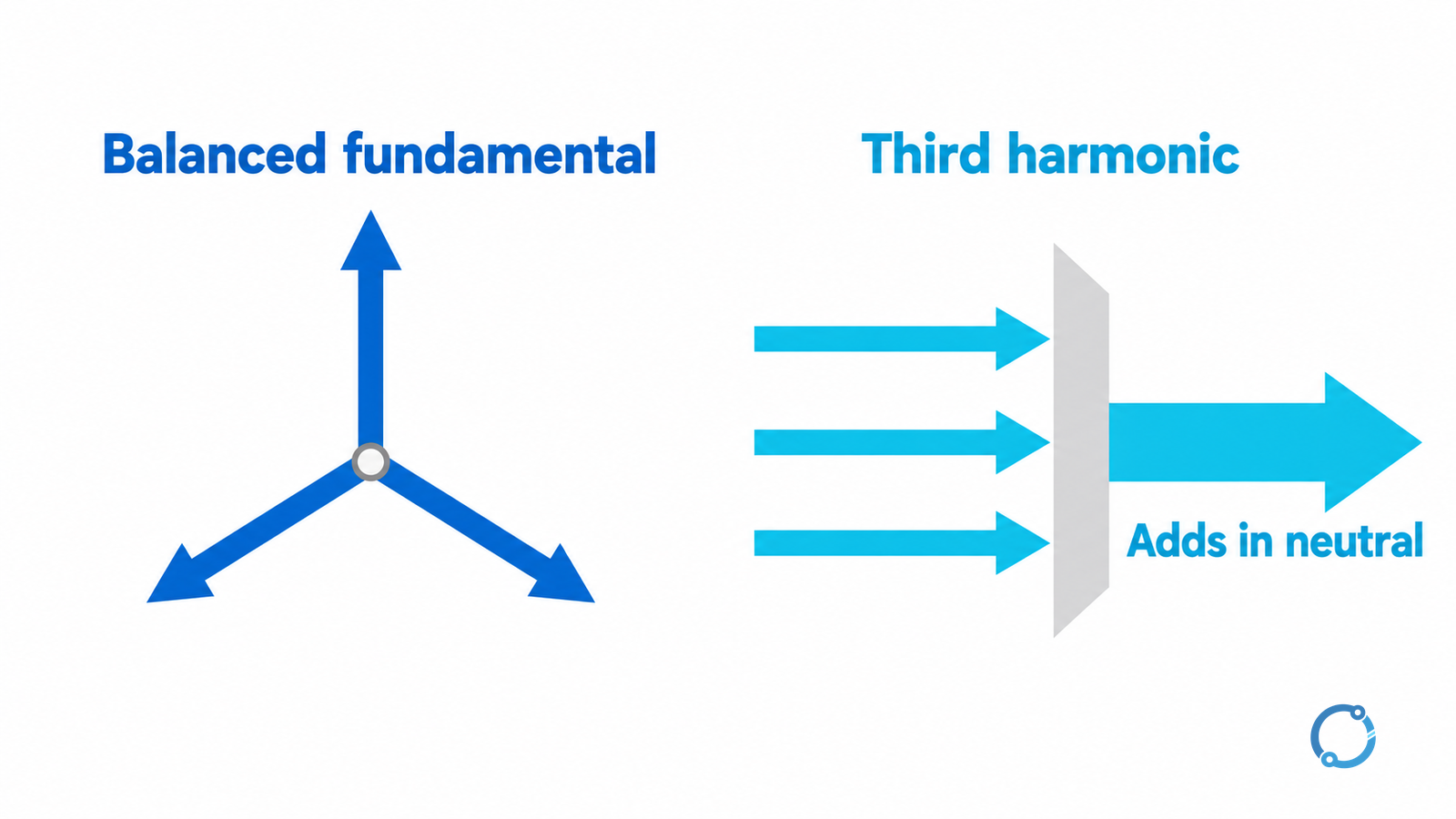
At the fundamental frequency, equal sinusoidal currents displaced by 120 electrical degrees have a zero vector sum. Unequal magnitudes or phase relationships leave a residual that flows in the neutral. A balanced nameplate total does not establish balance in each operating state: individual single-phase loads can switch independently.
The third harmonic behaves differently. For otherwise identical phase waveforms, multiplying the fundamental displacement by three produces 360 degrees. The corresponding third-harmonic components are in phase and add at the common neutral. Higher triplen components can also contribute; their actual magnitudes and phase relationships must be established rather than assumed.
The IET paper on harmonics, current ratings and voltage drop explains the triplen mechanism and its thermal significance. Published in 2007, it is used here for the underlying physics—not as proof of a current wiring-rule edition or permission to apply its tables to any cable.
An idealized example: neutral current greater than phase RMS current
Assume three identical single-phase nonlinear loads with:
- 100 A RMS fundamental current per phase, balanced and displaced by 120 degrees;
- 40 A RMS third-harmonic current per phase, with the three third-harmonic components in phase;
- no other harmonics and no other neutral-connected loads.
The fundamental neutral current cancels. The third-harmonic neutral current is:
IN,3 = 40 + 40 + 40 = 120 A RMS
Different frequency components combine by root-sum-square for RMS current in this idealized steady waveform. Each phase carries:
Iphase,RMS = √(100² + 40²) = 107.70 A
The neutral therefore carries 120 A while each phase carries approximately 107.70 A. This is a calculated teaching example, not measured OHELE field data. It shows why phase balance cannot be substituted for a neutral-current assessment; it does not specify any conductor area or derating factor.
If the fundamental currents become unbalanced, calculate their neutral residual and combine the resulting frequency components correctly. Do not simply add the RMS values of unrelated frequencies, and do not assume that every harmonic current adds arithmetically in the neutral.
Translate the current model into a design basis
| Question | Evidence needed before considering a reduced neutral |
|---|---|
| Which loads use the neutral? | Actual single-phase connections, operating combinations and future-load allowance |
| How balanced is the circuit? | Fundamental magnitude and phase relationships across credible operating states |
| What is the harmonic duty? | Neutral RMS current and relevant phase harmonic spectrum at representative loading |
| What installation heats the neutral? | Cable construction, loaded-conductor treatment, grouping, ambient and route conditions |
| How is it protected? | Applicable neutral protection requirements and the coordinated protective arrangement |
A meter showing three similar phase RMS values does not answer all these questions. Similar RMS values may conceal different waveforms, and the worst neutral duty may occur under a load combination different from peak total real power. Define the measurement or study scenarios before interpreting the results.
The neutral is another heat-producing conductor when it carries current. Its effect must be included in the applicable installed-cable thermal assessment; a phase-only ampacity assumption can miss that contribution. Do not infer a universal percentage reduction from the ratio of neutral current to phase current.
Wiring rules and overcurrent protection remain separate checks
IEC 60364-5-52, including its 2024 amendment, addresses wiring systems. The public summary of IEC 60364-4-43:2023 identifies neutral and midpoint overcurrent considerations, including triplen harmonics. These catalogue descriptions establish relevant subject areas, not a blanket permission to reduce a neutral.
The adopted national installation rules, conductor arrangement and protection conditions determine whether a reduction is permitted. A design that passes a current calculation can still fail a minimum-area or protection requirement. Conversely, specifying a full-size neutral does not automatically resolve unexpectedly high harmonic duty.
Use the separate feeder cable sizing guide for route and circuit coordination, and the circuit-breaker sizing guide for the protection boundary. Neither a phase breaker rating nor an assumed balanced load is sufficient evidence of neutral protection.
When the neutral-area decision is ready
The design record should state the load combinations considered, harmonic assumptions or measurements, resulting neutral duty, installed thermal model and governing wiring-rule basis. Any reduction must be justified against that record, including expected changes in nonlinear loads.
Qualified personnel must use safe procedures for surveys or modifications; never disconnect a loaded neutral to investigate its current. If the evidence is incomplete, hold the reduced-neutral decision. The useful answer is not “neutrals are smaller,” but “this neutral is suitable for the established current, thermal and protection duty.”