
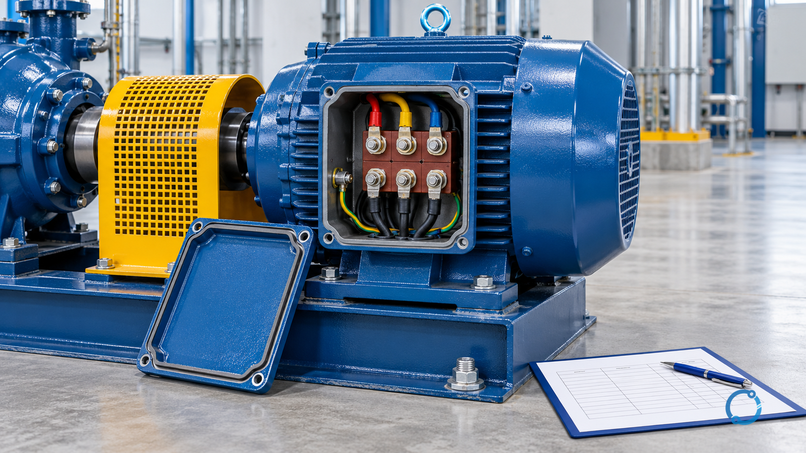
A three-phase motor is not diagnosed by one resistance reading, one insulation value or one current imbalance. Each test sees a different electrical property under a different condition. Resistance testing can reveal an open winding or a high-resistance connection, insulation testing can reveal a conductive path to the frame, and operating-current measurements can expose imbalance caused by the motor, supply or load. None is a complete winding diagnosis by itself.
The reliable approach is layered:
- establish a safe isolated state and record the motor and driven-system context;
- check all three phases with a repeatable resistance method;
- assess insulation only with the method, voltage and connections approved for that machine;
- compare current, voltage and mechanical evidence under a controlled operating state;
- join the results into a fault-family hypothesis rather than a single pass/fail label.
This article explains what those evidence layers can and cannot prove. It does not publish universal winding-resistance tolerances, insulation-resistance thresholds, current-unbalance limits or test voltages. Those depend on the motor design, nameplate, manufacturer data, test standard, winding temperature, test equipment and application.
The first answer: a fault family, not a verdict
Motor winding problems are often grouped into four overlapping families:
| Fault family | Typical electrical evidence | Important limit |
|---|---|---|
| Open phase or open winding | A phase circuit that is electrically open or much different from the others when tested by an approved method | A blown fuse, open contactor pole, damaged cable or loose terminal can imitate a winding failure |
| High-resistance connection | Unequal resistance or voltage drop across one path | The defect may be in the lead, lug, splice or internal connection rather than the winding itself |
| Turn-to-turn or coil short | Altered phase impedance, current imbalance, local heating, smell or degraded insulation | A basic insulation test may appear normal; the short can be internal to the winding |
| Winding-to-frame or winding-to-winding fault | Low insulation resistance or a conductive path found by an approved insulation test | A good or bad reading must be interpreted against the correct test setup and machine conditions |
Supply voltage imbalance, loose connections, rotor problems, bearings and mechanical load can produce symptoms that resemble one of these families. Conversely, a motor with a shorted turn may run for a period with only a modest current difference. The diagnosis must show which observations are consistent and which are not.
Gate 1: control the hazard before testing the winding
A motor is part of an electrical and mechanical system. Isolating the starter is not always enough. Check for:
- multiple supplies and backfeed through drives, generators, contactors or control circuits;
- a motor that can be rotated by the load, wind, pressure, gravity or another machine;
- residual voltage, stored energy and connected capacitors;
- automatic restart or remote start commands;
- exposed rotating parts and mechanical energy in the driven equipment;
- hot surfaces, process fluids and pressure that remain after electrical isolation;
- test leads and instruments suitable for the voltage and energy present.
Follow the site’s lockout/tagout, isolation and absence-of-voltage procedure. OSHA 29 CFR 1910.333 establishes electrical work-practice requirements for covered U.S. work; other jurisdictions and sites can add requirements. Do not disconnect a winding lead, open a terminal box or perform an insulation test while the motor is energized.
The motor must also be mechanically safe. For a coupled machine, the driven equipment may need to be blocked, uncoupled or otherwise controlled before shaft rotation or a winding test is attempted. The electrical test itself is not the only hazard.
Gate 2: record the machine and its operating context
Before interpreting a result, identify:
- manufacturer, frame, serial number and model;
- rated voltage, frequency, phase current, power factor and speed;
- connection: star, delta, six-lead, dual voltage or other;
- insulation class and temperature-rise basis;
- duty, starting method, number of starts and load type;
- drive, soft starter, contactor or direct-on-line control;
- protection settings and trip history;
- bearing type, coupling and driven equipment;
- recent rewind, modification, repairs or cable work;
- ambient, altitude, cooling and enclosure conditions;
- any vibration, noise, smell, smoke, heat or speed complaint.
The induction-motor calculation guide explains why nominal data must be evaluated together with the actual operating configuration. A motor selected for one connection and duty may be operated in another configuration by mistake. Before blaming the winding, verify that the installed connection matches the supply and the approved design.
Gate 3: isolate the complete phase circuit, not only the motor
Electrical tests can be made at several points: the motor terminal box, the starter outgoing terminals, the cable ends or a drive output. Each point answers a different question.
| Test location | What it can include | What it cannot separate |
|---|---|---|
| Starter outgoing terminals | Motor cable, terminal box, winding and connected accessories | Defects inside the starter or supply side, unless the circuit is properly disconnected |
| Motor terminal box | Motor winding and internal leads | Cable, remote starter and supply |
| Disconnected cable ends | Cable insulation and conductor continuity | Winding condition |
| Drive output disconnected and locked out | Motor-side circuit | Drive power section and control behavior |
Record exactly what was disconnected. A reading taken with a cable, capacitor, surge device, neutral, brake or control circuit still connected can be a reading of the whole arrangement, not the winding. Conversely, disconnecting a winding incorrectly can conceal a lead or terminal fault.
Use the motor manufacturer’s connection diagram. If multiple leads are marked U1, V1, W1, U2, V2 and W2, identify the correct pairs and connection state. A resistance measurement across the wrong pair can be entirely normal for the wiring configuration and entirely irrelevant to the suspected fault.
Gate 4: perform a balanced resistance check with a controlled method
Where the motor design and approved procedure permit resistance testing, test all three phases with the same instrument, range, lead arrangement and conductor temperature basis. A useful record includes:
| Measurement | Purpose |
|---|---|
| Phase-to-phase or winding-end resistance | Compare phase circuits and identify an open or high-resistance path |
| Lead resistance and instrument zero | Prevent test-lead resistance from dominating low readings |
| Contact condition | Identify unstable readings caused by a loose probe or contaminated terminal |
| Winding temperature | Compare resistance readings on a consistent temperature basis |
| Repeat reading | Confirm that the first result is stable and not an intermittent connection |
A low-resistance ohmmeter or four-wire method may be appropriate for very low winding resistance; a general-purpose multimeter may not have the resolution or test current needed. Follow the instrument and motor instructions. Do not use a resistance result to calculate temperature unless the material and method are valid.
If one phase is open, first check the motor leads, terminal block, cable and starter. A loose terminal can show the same electrical result as a broken winding lead. If one phase has higher resistance, inspect the connection path before condemning the winding. If the readings change when a lead is moved, the evidence points to a connection fault or unstable test setup rather than a stable winding resistance difference.
What resistance can show
A balanced resistance check is strong evidence against a simple open winding circuit when the test includes the correct leads and is performed correctly. It can help identify gross imbalance and obvious open-phase conditions. It cannot prove that every turn is sound. A few shorted turns can change the magnetic and thermal behavior of the machine while leaving the DC resistance apparently similar.
What resistance cannot show
Resistance does not, by itself, prove:
- that insulation is healthy;
- that a turn-to-turn short is absent;
- that the rotor is sound;
- that the supply is balanced;
- that the driven load is correct;
- that a VFD or starter is switching every phase correctly;
- that a cable or contactor is not heating under operating current.
These limits are why the next evidence layer matters.
Gate 5: assess insulation with the correct method
Insulation resistance testing measures a current through or across insulation when a test voltage is applied. It can provide evidence of a conductive path to frame, moisture ingress, contamination or damaged winding insulation. It is not a complete proof of winding integrity.
Before testing:
- isolate and verify the complete motor circuit;
- disconnect sensitive equipment, drives, surge devices and control circuits as required by their instructions;
- make sure the motor and cable are in the correct state for the test;
- select a test voltage from the machine and manufacturer guidance, not a random voltage;
- keep people away from the test circuit;
- discharge stored energy after the test;
- use a tester with a suitable voltage and range;
- record temperature, humidity, test duration and connection point.
IEEE P43 is an active revision project for insulation-resistance testing of rotating-machine windings rated 750 W or greater, while IEEE 43-2013 remains available as an inactive-reserved standard. The existence of a standard does not replace the manufacturer’s test instructions. The class of insulation, winding age, moisture, temperature and prior history must be part of the interpretation.
A high insulation resistance reading does not exclude a turn-to-turn fault. The test voltage may not expose a local short inside the winding, and the resistance measurement can be dominated by the healthy insulation area. A low reading may also be caused by moisture, contamination, connected electronic equipment or a damaged cable, not necessarily a motor winding failure.
Do not use a generic “minimum megohm” number from an unrelated motor or a web table. A threshold without test voltage, temperature, machine class and history can be dangerously misleading. The insulation resistance testing guide provides the general measurement principles; the motor manufacturer and the applicable standard control motor acceptance criteria.
Gate 6: use operating current as corroboration, not proof
Current unbalance can indicate a winding fault, but it can also come from supply voltage unbalance, single-phasing, unequal impedance in the feeder, a contactor problem, a VFD output issue or mechanical load variation. A current reading becomes much more useful when it is recorded with the corresponding voltage and operating state.
Record:
- simultaneous phase currents, not one phase after another at different loads;
- phase-to-phase and phase-to-neutral voltages where relevant to the supply configuration;
- motor speed, load and process condition;
- drive frequency, carrier settings and current waveform if applicable;
- ambient and winding temperature;
- duration and repeatability of the condition;
- starting current, acceleration time and transition points;
- power factor or power measurement from a suitable instrument.
A clamp meter’s measurement uncertainty becomes important when the phases are close to balanced. A small difference displayed on one range may not be meaningful without a defined instrument resolution and measurement method. Do not subtract voltages or currents mentally and call the difference a fault signature without checking instrument accuracy.
The voltage unbalance measurement guide explains why nominal phase voltage alone is insufficient. The motor reacts to the sequence and magnitude of the supply voltages, not just to an average. A motor with a healthy winding can draw unbalanced current when the supply is unbalanced.
Current signature and spectral methods
Motor-current signature analysis and other spectral methods can be valuable for specific fault patterns, but they are specialist tools. Do not treat a single spectrum peak, a smartphone app or a generic threshold as proof of a shorted turn. Interpretation depends on:
- motor design and slot harmonics;
- supply frequency and waveform;
- drive modulation and variable speed;
- load oscillation;
- sensor type, placement and sampling;
- speed and pole count;
- time record length and analysis settings;
- baseline data collected under comparable conditions.
Use current-signature analysis as supporting evidence where a qualified specialist, valid measurement setup and reference data exist. It should not replace resistance, insulation, supply and mechanical checks.
Gate 7: test the entire motor system for non-winding causes
Winding symptoms can be reproduced by the surrounding system:
| Observed symptom | Alternative cause to check |
|---|---|
| High current on one phase | Supply voltage imbalance, loose cable termination, contactor pole, capacitor, drive output or winding problem |
| Overheating without current imbalance | Cooling restriction, high ambient, overload, excessive starts, blocked fan, incorrect duty or bearing friction |
| Tripping at start | Mechanical load, locked rotor, starting method, contactor transition, protection setting or supply capacity |
| Noise and vibration | Bearing, rotor, coupling, alignment, foundation, load or electrical signature |
| Intermittent current | Loose connection, failing contactor, cable movement, moisture or control instability |
| Good insulation but poor running performance | Shorted turns, rotor defect, voltage quality, wrong connection, load mismatch or measurement problem |
Check the driven equipment before removing the motor. A jammed pump, damaged gearbox, failing fan or binding conveyor can look like a motor overload. The motor operating-temperature diagnosis provides a structured way to separate ambient, cooling and load effects. Electric motor noise diagnosis and motor replacement checks cover adjacent mechanical and selection questions.
If a drive is involved, follow its isolation and testing instructions. The drive’s DC bus may retain energy, and the motor cable can carry high-frequency voltage. A conventional low-frequency insulation test may be unsuitable for equipment containing surge protection, filters or a connected drive. The test method must be compatible with the complete assembly.
Gate 8: map the evidence before deciding to rewind or replace
Create a fault-evidence table:
| Evidence | Consistent with winding fault? | Other explanation? |
|---|---|---|
| One winding open | Yes, if leads and terminals are proved sound | Cable, starter or terminal connection |
| All phase resistances similar | May still hide a turn-to-turn fault | Need insulation, operation and specialist evidence |
| Insulation to frame reduced | Possible ground fault or moisture/contamination | Disconnected equipment, cable, test method or surface condition |
| Insulation high, motor still overheats | Does not exclude turn-to-turn or rotor/load fault | Verify current, supply, cooling and mechanical load |
| Current unbalance with voltage balance | Possible winding or connection fault | Instrument, contactor, cable, rotor or phase impedance |
| Current imbalance tracks source voltage imbalance | Not diagnostic of winding fault alone | Correct supply or compare under controlled conditions |
Only after the table is assembled should the repair strategy be chosen. A rewind may be appropriate when the winding is confirmed faulty and the mechanical condition supports it. A replacement may be better when the insulation system, rotor, bearings, efficiency, duty or spare-parts situation makes repair uneconomic or unsuitable. The motor repair versus replacement decision connects electrical findings with lifecycle decisions.
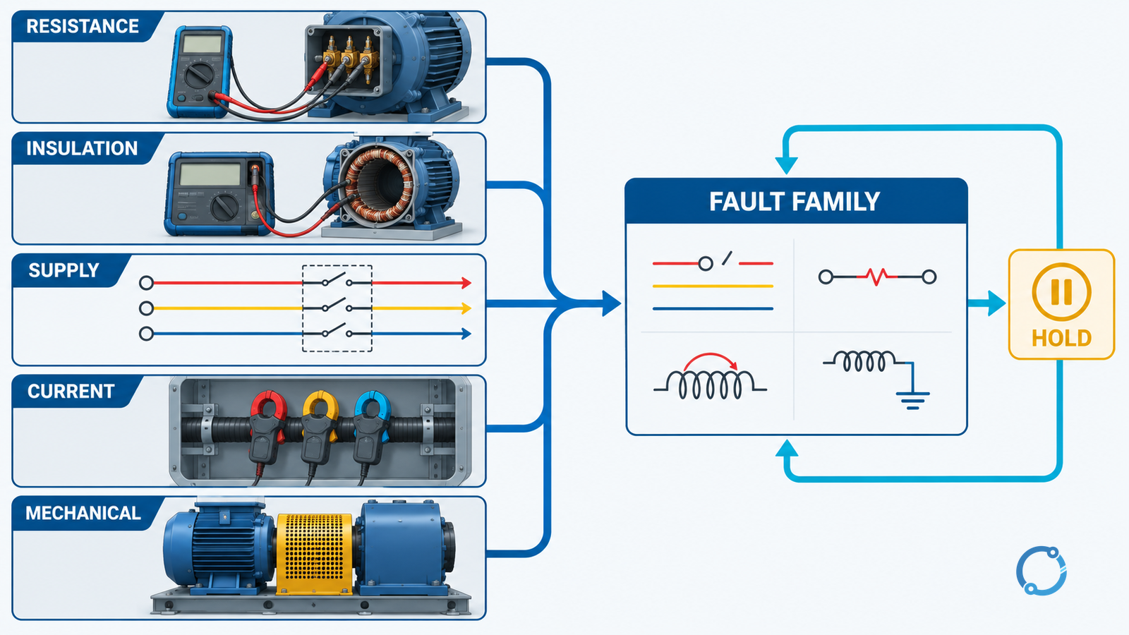
Which measurements require which state?
A common source of bad diagnosis is mixing test conditions. Keep the state explicit:
De-energized and isolated
- winding resistance and lead continuity;
- insulation resistance, if the equipment and manufacturer permit the test;
- cable isolation and connection checks;
- visual inspection of terminals, leads and insulation.
Energized, under an approved operating procedure
- three-phase voltage and current;
- power, power factor and frequency;
- starting current and acceleration behavior;
- temperature and vibration;
- drive input and output data within the instrument’s permitted connections.
Rotating or mechanically stored energy
- speed, load and torque behavior;
- bearing, rotor and driven-equipment signatures;
- coast-down or blocked-rotor evidence only where the approved procedure and equipment permit it.
Never take an energized measurement merely because a clamp meter is convenient. Qualified personnel must use an approved work procedure, suitable test equipment, barriers, PPE and a location from which the measurement can be performed safely.
Recognition and escalation
Escalate the investigation when:
- the winding has visible charring, broken leads or a burning smell;
- insulation resistance changes suddenly or cannot be tested safely;
- a protection device trips repeatedly without a confirmed circuit cause;
- current imbalance is accompanied by overheating or smoke;
- the motor is connected through a drive whose output or energy state is not understood;
- the driven machine cannot be secured or isolated;
- the test instrument is not suitable for the motor, cable or drive;
- the result conflicts with the motor’s operating behavior;
- a rewind or replacement decision depends only on one test.
A motor that restarts successfully after cooling is not proved healthy. Thermal cycling can temporarily change the resistance of a damaged connection, and a small turn-to-turn fault may remain. Record the recurrence and compare it with the same load, ambient and supply state.
Handover and verification
After repair or replacement:
- verify the winding connection and lead identification;
- repeat balanced resistance tests with the documented method;
- complete the approved insulation tests and discharge procedure;
- inspect terminals, cable, glands and enclosure;
- confirm correct supply voltage, phase sequence and drive settings;
- run the machine through the approved no-load or controlled-load steps;
- compare current, voltage, temperature and vibration with the baseline;
- verify protection settings and trip functions;
- record the remaining uncertainty and the basis for release.
The handover record should allow another engineer to see why the motor was repaired, replaced or returned to service. “Megger was good” or “resistance looked equal” is not sufficient evidence.
The practical conclusion
Three-phase winding faults are diagnosed by combining evidence, not by choosing the most convenient meter. Resistance checks can locate open or high-resistance phase circuits, insulation tests can expose a path to the frame or moisture-related deterioration, and current measurements can show an operating imbalance. Each result has blind spots.
Use safe isolation, the exact motor connection, the correct instrument and the manufacturer’s test basis. Then combine winding evidence with supply, cable, contactor, drive and mechanical-load evidence. If the cause remains uncertain, preserve the test record and escalate rather than repeating starts until the motor fails more clearly.