
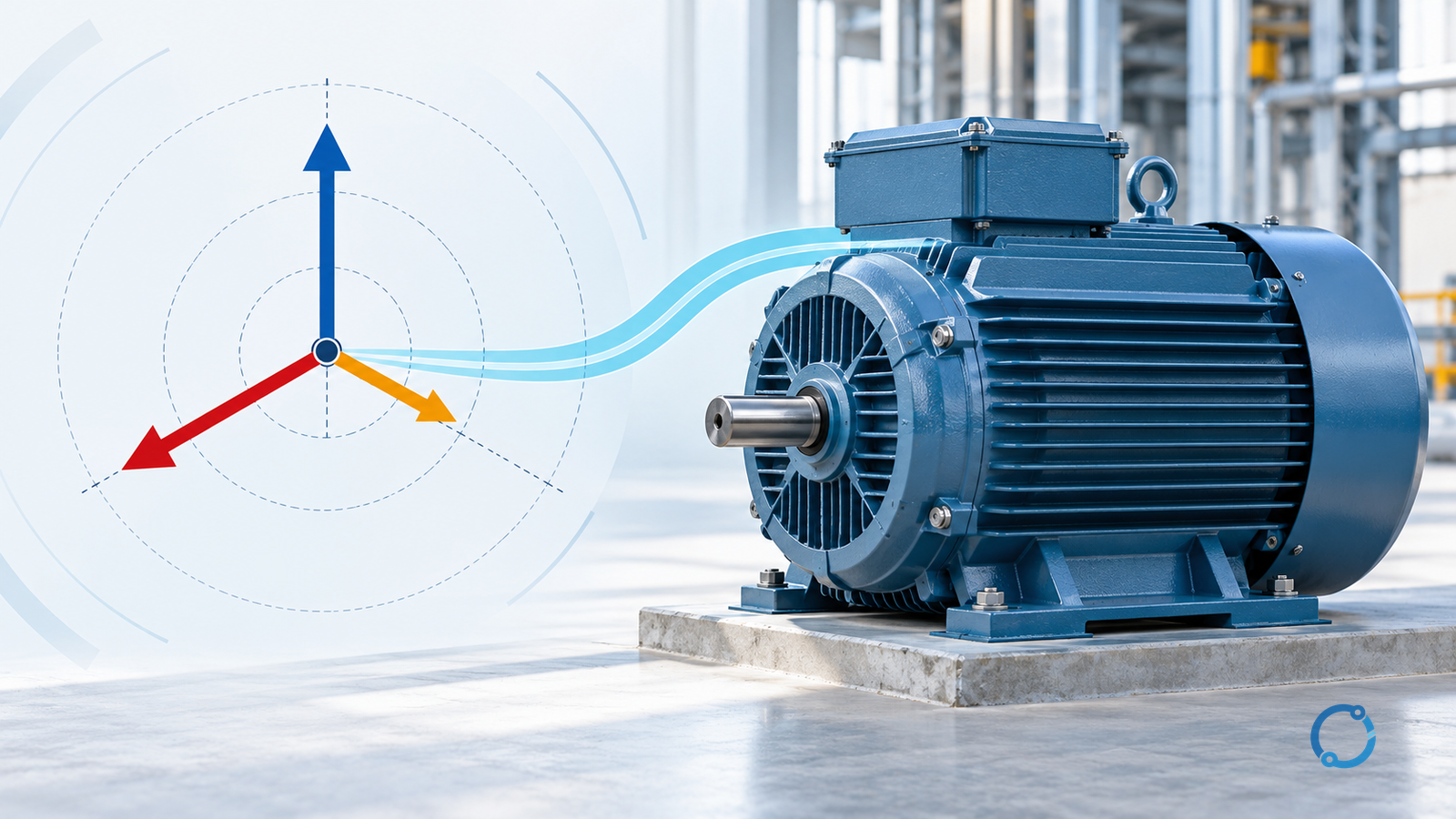
Voltage unbalance is a property of the three-phase voltage set, not a label for one low phase or one voltage fluctuation. To measure it defensibly, first decide whether the result will be a line-to-line magnitude screen or a symmetrical-component calculation. The percentages are not interchangeable.
This explanation covers three-phase supply measurements at motor terminals and upstream distribution points. It distinguishes line-to-line from phase-to-neutral voltage, explains negative-sequence motor effects, and sets out a safe diagnostic path. It gives no universal acceptance limit, derating table or energized-work procedure.
Define the voltage set before calculating
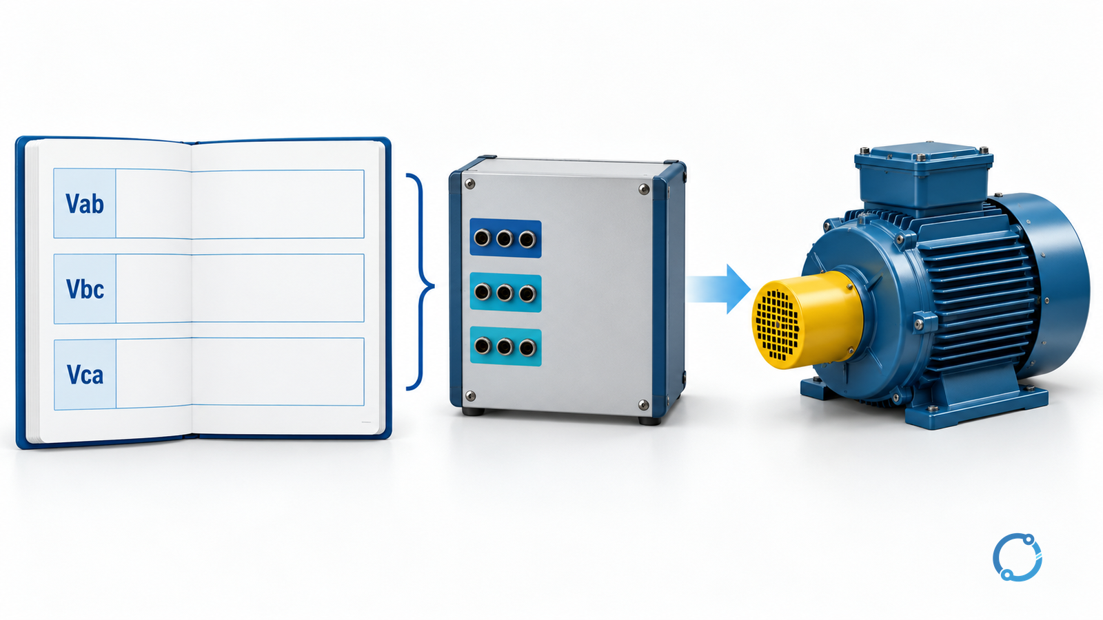
Use these quantities and symbols consistently:
| Symbol | Quantity | Unit and reference |
|---|---|---|
Vab, Vbc, Vca |
Line-to-line RMS voltage magnitudes | V, measured between named conductors |
Va, Vb, Vc |
Phase-to-neutral fundamental-frequency voltage phasors | V and degrees, common reference |
V1 |
Positive-sequence voltage component | V |
V2 |
Negative-sequence voltage component | V |
V0 |
Zero-sequence voltage component | V |
a |
Phase operator | Dimensionless, equal to 1 at +120 degrees |
Umag |
Line-voltage magnitude unbalance, DOE/NEMA definition | % |
U2 |
Negative-sequence voltage ratio | % |
The subscript labels are not interchangeable. Vab is a line-to-line quantity. Va is a phase-to-neutral phasor only when a valid neutral or reference exists and the measurement is made that way. Meters may display numbers with the same unit while representing different electrical quantities.
Phase angles require one time reference. Separate handheld readings taken at different instants do not provide synchronized angles. Use an instrument that samples all three channels together or a recorder that preserves their relationship. Record phase labels, rotation, terminal, range and whether values are RMS, fundamental-frequency or another basis.
Calculate the line-to-line magnitude screen
The U.S. Department of Energy (DOE), attributing the definition to NEMA, describes percent voltage unbalance as 100 times the absolute maximum deviation of the line voltages from their average, divided by that average. With line-to-line RMS magnitudes:
Vavg,LL = (Vab + Vbc + Vca) / 3
DeltaVmax = max(|Vab - Vavg,LL|, |Vbc - Vavg,LL|, |Vca - Vavg,LL|)
Umag = 100 x DeltaVmax / Vavg,LL
Use each absolute deviation; the largest may belong to the lowest phase. This screen uses three line-to-line magnitudes and no phase angles.
For a worked comparison, assume a hypothetical synchronized phase-to-neutral set:
Va = 230 at 0 degrees V
Vb = 220 at -120 degrees V
Vc = 225 at +120 degrees V
For that same assumed set, the line-to-line magnitudes are:
|Vab| = |Va - Vb| = 389.744 V
|Vbc| = |Vb - Vc| = 385.389 V
|Vca| = |Vc - Va| = 394.049 V
Their average is 389.727 V. The largest deviation is 389.727 – 385.389 = 4.338 V, so:
Umag = 100 x 4.338 / 389.727 = 1.113%
That is a teaching calculation, not a field measurement or pass/fail decision. It shows which quantity the percentage normalizes but cannot establish acceptability for a particular motor or supply.
Calculate negative-sequence voltage from phasors
Symmetrical components decompose the phase quantities into positive-, negative- and zero-sequence sets. For a consistent phase-to-neutral set:
V1 = (Va + a Vb + a^2 Vc) / 3
V2 = (Va + a^2 Vb + a Vc) / 3
V0 = (Va + Vb + Vc) / 3
The negative-sequence voltage ratio is:
U2 = 100 x |V2| / |V1|
Those equations apply to a coherent phase-to-neutral set with a defined reference. With line-to-line phasors, use the corresponding line-to-line transformation or an instrument result whose basis is stated; do not substitute Vab, Vbc and Vca directly into the phase-to-neutral equations. A three-wire line-to-line set carries no unique zero-sequence information.
With a = 1 at +120 degrees, the sample set gives:
|V1| = 225.000 V
|V2| = 2.887 V
U2 = 100 x 2.887 / 225.000 = 1.283%
|V0| = 2.887 V
The nonzero zero-sequence value is important. The phasors do not sum to zero, so the sample contains a common-mode component. That does not invalidate the calculation, but it shows why the result cannot be relabelled as a three-wire line-to-line result without checking circuit and basis.
The 1.113% magnitude result and the 1.283% negative-sequence result differ because they normalize different quantities. The first divides the largest line-voltage magnitude deviation by average line voltage. The second divides the negative-sequence phasor by the positive-sequence phasor. Similar-looking numbers do not prove that the definitions agree.
Keep phase-to-phase and phase-to-neutral data separate
Phase-to-phase, or line-to-line, voltage is measured between two phase conductors. Phase-to-neutral voltage is measured between a phase conductor and a defined neutral reference. In a four-wire system, phase-to-neutral readings can reveal neutral shift or zero-sequence content. Delta, ungrounded or isolated circuits may offer no valid neutral reference for the intended calculation.
Phase-to-ground readings are not automatically phase-to-neutral readings. Ground potential, capacitance, grounding impedance and common-mode voltage can influence what the instrument reports. Subtracting scalar phase-to-ground magnitudes does not give line-to-line voltage; phasor subtraction requires synchronized complex quantities on a common reference. Do not mix references in one synchronized set.
For a motor-terminal screen, line-to-line measurement is usually the clearest common basis because it does not depend on a neutral connection. If zero-sequence information matters, use the appropriate circuit model and a point where the neutral or reference is defined. Record that choice with the result.
Choose a representative measurement interval
Unbalance is not necessarily constant. Single-phase lighting, welders, office loads, process changes and intermittent equipment can alter the phase relationship. One snapshot may describe an operating state but not the condition that overheats a motor.
Capture the voltage set at the motor terminals while the motor runs at a representative load. Record load or current, speed or process state, time, duration, phase rotation, terminal and any switching during the interval. If the load varies, compare equal load bands rather than idle and full-load readings.
For a power-quality recorder, retain simultaneous channel data and the fundamental-frequency result. A long interval can expose recurring events, but an average can hide a short maximum. Report the averaging period, sampling method and statistic. Do not enter reported minimum, maximum and average values into one phasor calculation.
Compare upstream and downstream locations on the same basis. Service-entrance, MCC and motor-terminal readings taken at different times can suggest a location; synchronized records are stronger evidence. The DOE motor guide recommends checking voltage balance at several distribution locations before deciding that the motor is the source.
Converter output is a separate measurement problem. A general-purpose mains analyzer may not represent the fundamental voltage set at a PWM output; drive settings, filters and cable effects can change the waveform. Use the motor and drive documentation and an approved method for that equipment. Do not carry a mains-supply percentage directly onto a converter output without establishing comparability.
Explain the motor effect through negative sequence
An induction motor responds to the positive-sequence voltage by producing forward torque. The negative-sequence component rotates opposite to the rotor’s forward field. The resulting reverse-field component produces additional rotor current and loss, and can create torque pulsation and vibration. The exact consequences depend on motor design and operating point; a voltage percentage alone does not establish them.
DOE’s motor-systems guidance notes that voltage unbalance can produce current unbalance much larger than the voltage unbalance, along with torque pulsation, increased loss, lower efficiency and overheating. That is a causal warning, not a universal conversion formula. The same guidance recommends a below-1% terminal-voltage screening target and refers to NEMA derating material for higher values. Treat that as dated guidance tied to its cited edition, not a limit for every motor, duty or jurisdiction.
If the voltage set is balanced but current is strongly unbalanced, the motor or local circuit becomes a more credible hypothesis. If voltage unbalance is present upstream and at the motor terminals, a supply or distribution cause is more credible. These are diagnostic directions, not conclusions from one reading. The motor operating-temperature diagnostic method is the appropriate next step when the question is whether a temperature change comes from cooling, load, voltage quality or another cause.
Respect the NEMA and IEC boundaries
The DOE definition above is a line-voltage magnitude definition. It is often called a NEMA-style unbalance calculation because the DOE tip sheet attributes it to NEMA guidance. NEMA MG 1 also contains motor-family sections on unbalanced-voltage effects and derating, including sections 14.36 and 20.24 in the public Part 0 table of contents for ANSI/NEMA MG 1-2016 (Revision 1, 2018). Its public Revision 1 summary also cross-references supply unbalance above 1% as an unusual service condition.
IEC 60034-26:2026 is the current second edition of the IEC publication describing the effects of unbalanced voltages on three-phase cage induction motors. The official IEC catalogue description says the new edition clarifies that the relevant voltages are line-to-line in Clause 4, Annex A and Annex B. That supports basis labelling; it does not make every NEMA and IEC percentage, derating figure or acceptance criterion identical.
If a specification or motor nameplate cites a standard, use the edition and definition named there. Do not relabel a NEMA-style magnitude percentage as a negative-sequence percentage and compare it with an IEC limit. Do not scale a limit by the ratio between the two example percentages; that would turn a teaching comparison into an unsupported rule.
Trace the cause in a safe order
Electrical measurements and repairs require qualified, authorized personnel, suitable instruments, the site risk assessment and the applicable isolation procedure. OSHA’s electrical work-practice rule and hazardous-energy control rule are references for the U.S. general-industry boundary, not permission to bypass local procedures. Do not open a terminal box, probe live conductors or touch a rotating motor to obtain a reading.
After verifying the measurement basis, use this sequence:
| Stage | Evidence to collect | Decision it supports |
|---|---|---|
| Measurement quality | Simultaneous channels, known phase labels, suitable range, stable leads, correct voltage reference | Whether the percentage is credible enough to investigate |
| Source reference | Service-entrance or utility-point voltage on the same basis and comparable time | Whether unbalance is upstream of the facility |
| Load pattern | Single-phase loads, welders, lighting, large intermittent equipment and switching times | Whether the unbalance follows a load or operating cycle |
| Distribution path | Upstream and downstream readings, transformer tap or bank condition, capacitor-bank state, fuse and contactor condition | Which feeder, transformer or compensating equipment deserves inspection |
| Connection condition | Approved isolated resistance checks and termination inspection; authorized voltage-drop or thermal measurements where justified by site work controls | Whether a high-resistance or open connection is contributing |
| Motor/local condition | Current balance, winding resistance or inductance checks, insulation and mechanical evidence collected by qualified personnel | Whether the motor or driven equipment remains a credible cause |
Start with the least invasive evidence and stop when the data no longer support a conclusion. No single thermal image, voltage reading or loose terminal proves the source. Motor replacement does not correct a supply problem; a capacitor change does not correct a damaged winding.
Correct the supported cause and retest
Corrective action follows the supported cause: redistribute single-phase loads, repair a verified connection defect, review transformer tap selection, investigate capacitor-bank operation, coordinate with the utility, or repair or replace the motor when the evidence supports it. Each action has its own switching, protection and process consequences, so the work needs an approved procedure and a qualified owner.
Retest at the same terminal, on the same phase basis, at a comparable load and over a comparable interval. Record the before and after voltage set, current balance, motor temperature trend and any changed operating condition. The voltage-sag and swell guide addresses short-duration voltage events, which are a different power-quality question. If the motor must be replaced rather than corrected, use the replacement-interface review to check the new duty, supply and connection requirements.
The investigation is complete when the measurement basis is documented, the calculation is reproducible, the cause is supported by evidence and the retest demonstrates that the selected correction works under the intended operating state. A lower percentage is useful evidence; it is not proof that every motor, connection and process condition is healthy.
Sources
- U.S. DOE – Eliminate Voltage Unbalance, Motor Systems Tip Sheet #7
- U.S. DOE – Premium Efficiency Motor Selection and Application Guide
- IEC 60034-26:2026 – Effects of unbalanced voltages on three-phase cage induction motors
- ANSI/NEMA MG 1-2016 (Revision 1, 2018) – public Part 0
- OSHA 29 CFR 1910.147 – control of hazardous energy
- OSHA 29 CFR 1910.333 – electrical work practices