
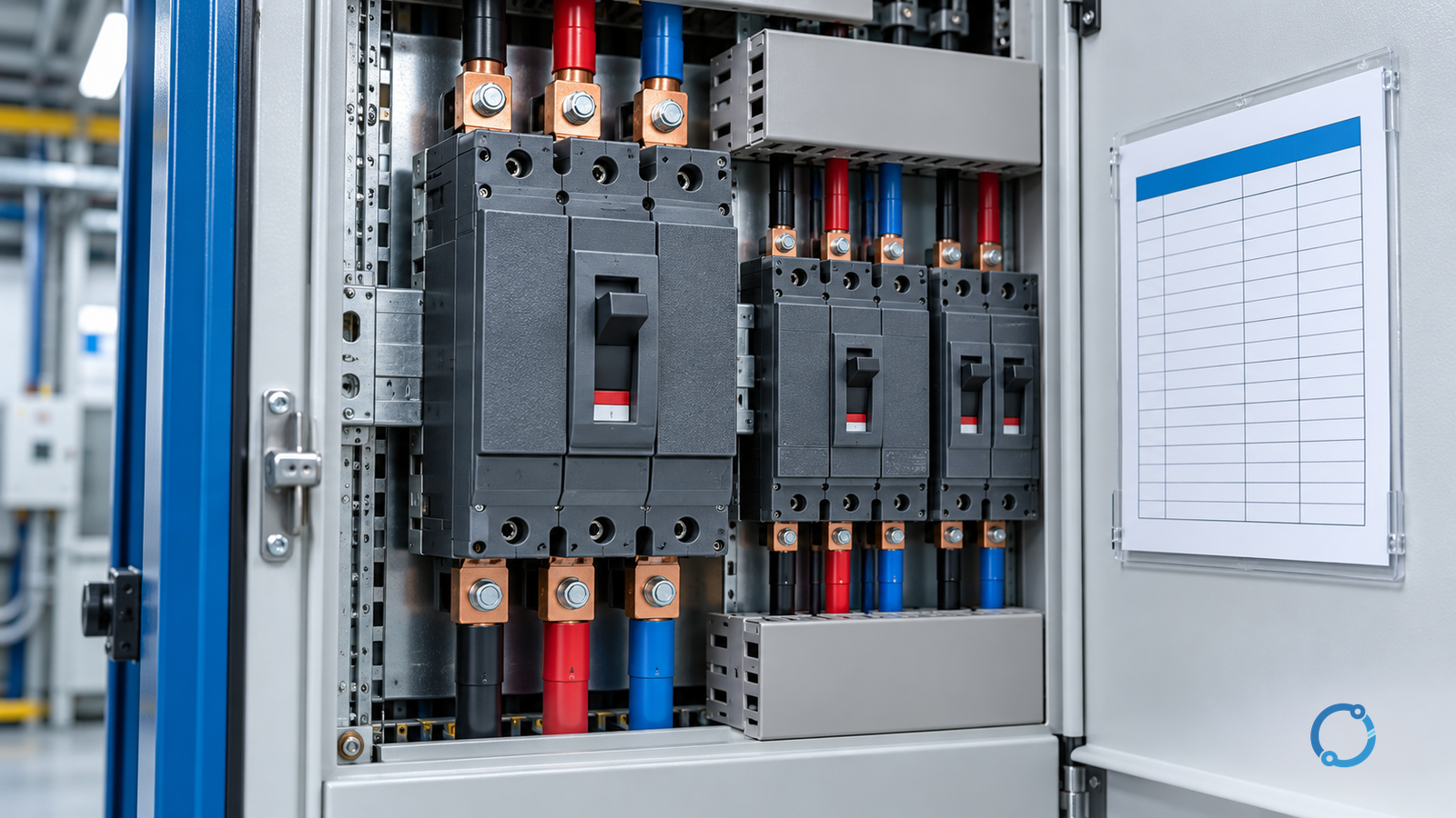
A molded-case circuit breaker trip is an outcome, not a diagnosis. The open handle tells you that the breaker changed state. It does not prove that the load was too large, that the trip unit was faulty, or that a short circuit occurred. The operating handle on many MCCBs does not identify which internal function caused the trip, and pressing it back to ON does not prove the circuit is safe.
The useful question is: what evidence existed before, during and after the trip? Preserve that evidence first. Record the operating state, protection indication, load conditions and environmental history. Then isolate the circuit under the site procedure and determine whether the event is consistent with overload, a trip-unit action, a thermal or mechanical problem, or a short-circuit or earth-fault condition.
This article is a diagnostic framework for qualified electricians and engineers. It does not provide a universal reset limit, trip-curve table or permission to energize an uncertain circuit. The exact MCCB instruction, protection study, control scheme and applicable electrical safety rules govern the work.
Start with the event, not the handle
The first person at the panel often has one goal: restore power. That instinct can erase the most useful evidence. Before touching the handle, collect basic facts:
- which breaker tripped, and which upstream or downstream devices also operated;
- whether the trip occurred at starting, during normal load, after a load step, during a transfer or after a disturbance;
- the time and duration of the trip;
- whether it was the first event or part of a repeat pattern;
- the handle, flag, display, alarm or communication status;
- motor starters, contactors, drives and control outputs that changed state;
- ambient temperature, enclosure doors, ventilation and nearby heat sources;
- connected load and whether equipment was added or reconfigured;
- any overload, short-circuit, earth-fault, arc-flash or power-quality indication;
- the identity of the exact breaker, trip unit, rating plug and firmware;
- photographs of the panel before any reset or adjustment.
An electronic trip unit may retain a cause-of-trip indication, event log, current history or communication alarm. A thermal-magnetic MCCB may provide only a trip flag or no explicit indication at all. That difference changes the evidence available, not the safety rule. The MCCB basics guide explains the device family, while the LV protective-device ratings guide explains why voltage, current and breaking capacity need separate checks.
Why repeated reset attempts are the wrong test
Repeatedly reclosing a breaker is sometimes described as “seeing whether it holds.” For an unknown fault, this is an uncontrolled series of electrical tests performed through the equipment being protected. Each attempt can:
- deliver another fault current to damaged insulation or a loose connection;
- increase arcing and thermal damage;
- stress the breaker and downstream equipment;
- reset or obscure electronic trip information;
- start a motor or process unexpectedly;
- expose personnel to arc flash, mechanical motion or released energy;
- turn an intermittent condition into a permanent failure.
OSHA 29 CFR 1910.334 prohibits repetitive manual reclosing of a breaker into a circuit with an unknown condition within its U.S. scope, apart from the limited conditions in the standard. The principle is broadly applicable: a resettable handle is not a diagnostic instrument.
Do not bypass the breaker, hold the handle closed, change the trip setting merely to keep it from operating, or replace the device with a larger one before the cause is known. A larger breaker can make the equipment less protected while hiding the original defect.
Gate 1: establish a safe work condition and preserve the scene
The investigation begins with electrical safety. Make the equipment and area safe, notify affected operations, prevent unexpected starting and follow the site’s lockout/tagout, isolation and verification procedure. In the United States, OSHA 29 CFR 1910.333 establishes the selection and use of safe electrical work practices for covered installations.
Before inspection, consider:
- whether an upstream source can backfeed the MCCB through a generator, UPS, drive, capacitor bank or parallel feeder;
- whether the panel has stored energy, compressed springs or a motor-operated mechanism;
- whether the load must be mechanically restrained before electrical work;
- whether the surrounding process has created heat, moisture, gas or chemical contamination;
- whether the breaker changing state can initiate an automatic restart;
- whether the equipment is under a functional-safety or process-safety control that requires authorization before testing.
Do not open an enclosure that may contain energized parts merely to look for burn marks. Use the approved voltage verification and PPE regime. Once safe, inspect for obvious smoke, melting, loose terminals, damaged conductors, moisture, corrosion, foreign objects and mechanical binding.
Gate 2: identify the exact protection function
“MCCB” includes several internal architectures. A thermal-magnetic device may use a bimetal element for overload and a magnetic element for short-circuit current. An electronic trip unit may calculate current or heat-related quantities and may include short-time, instantaneous, ground-fault, neutral or zone-selective functions. A motor-rated device or an MCCB with a replaceable trip unit can have dedicated settings that are not interchangeable with a general-purpose breaker.
Record:
| Device identifier | What to capture |
|---|---|
| Frame and model | Manufacturer, family, catalogue number and revision |
| Pole count | Three-pole, four-pole, switched neutral or other configuration |
| Rated current | Frame rating, sensor rating, rating plug and protected current |
| Breaking capacity | Voltage, fault level and product marking basis |
| Trip type | Thermal-magnetic, electronic, motor-protection or hybrid |
| Protective settings | Long-time, short-time, instantaneous, ground-fault and neutral settings |
| Accessories | Shunt trip, undervoltage release, auxiliary switch, motor operator, communications |
| Environment | Ambient rating, enclosure type, altitude and mounting conditions where relevant |
| Installation | Feeder or branch, grounding arrangement, load type and upstream protection |
The MCCB selection guide for APFC panels shows why the same frame cannot be selected from one current number. Capacitor switching, harmonic duty and inrush conditions change the device and protection requirements.
Gate 3: determine what the trip indication can and cannot tell you
Some devices identify a trip cause; others do not. A trip flag may indicate that the mechanism operated, but not distinguish an overload from an instantaneous trip. An electronic unit may show long-time, short-time, instantaneous, ground-fault or self-protection status. The exact interpretation is product-specific.
Treat a displayed cause as an electronic event code, not as the physical root cause. A short-time or instantaneous flag still requires investigation of the circuit. A long-time indication is consistent with high load, but it may also be caused by a locked rotor, poor cooling, incorrect rating plug, damaged terminals, harmonics or an ambient correction issue.
Do not clear event memory or power-cycle a trip unit before retrieving the information required by the manufacturer’s procedure. If the device communicates with a protection system, preserve the event and time synchronization record. The same discipline applies to breaker trip troubleshooting in substations, although the scale and protection architecture differ.
Gate 4: compare the trip with the load’s real operating profile
A trip is only consistent with overload when the current and time history support a thermal overload condition. The comparison should include:
- motor starting current and duration;
- acceleration torque and mechanical load;
- repeated start frequency and duty cycle;
- process steps that create a temporary overload;
- neutral current and harmonic content;
- ambient temperature in and around the enclosure;
- mutual heating from adjacent devices;
- supply voltage and phase balance;
- breaker and conductor installation method;
- trip-unit rating and setting relative to the manufacturer’s curves.
Motor circuit protection illustrates why a single full-load current is insufficient. An MCCB or motor protection device must allow the expected starting current without losing the ability to protect against stalled or overloaded operation. If the trip occurs only during a particular start or load step, the process sequence and mechanical condition become part of the breaker diagnosis.
For an electronic trip unit, preserve the protection study and settings. For a thermal-magnetic MCCB, compare the device’s published trip band and the actual installation conditions. Do not use a screenshot of a generic curve as proof. Curves depend on the exact catalogue number, trip unit, ambient compensation, frequency, waveform and voltage.
Gate 5: inspect heat, terminals and installation conditions
An MCCB is part of a thermal system. It can trip in a correctly loaded circuit because the actual conditions differ from the design assumptions. Inspect:
- supply and load terminations for discoloration, thermal damage or contamination;
- conductor preparation, strand damage and connector compatibility;
- terminal torque as specified by the exact equipment instruction;
- breaker mounting and mechanical alignment;
- ventilation, filters, doors and enclosure temperature;
- grouping, spacing and barriers;
- heat sources such as braking resistors, drives, transformers or process equipment;
- dust or lint that blocks cooling paths;
- water ingress, corrosion and condensation;
- whether a fan or air-conditioning system has failed.
A hot terminal can transfer heat into the breaker and make it trip earlier than the load alone suggests. A cool external enclosure does not prove that the breaker interior is within its rating. Conversely, a thermal spot on a terminal may be the result of a loose connection rather than the cause of the trip. LV switchgear operating-temperature diagnosis explains how ambient, enclosure and load effects are separated.
Do not use a generic torque value from a different product. Use the MCCB and lug instructions, the correct tool, the recommended conductor termination and an appropriate inspection method. Re-tightening a damaged joint is not a repair if strands, threads or plating are compromised.
Gate 6: rule out short-circuit, earth-fault and insulation failures
An instantaneous trip can be consistent with a short circuit, a high inrush event or a trip-unit action. It is not proof of any one of them. Look for evidence along the entire circuit:
- damaged or crushed cable insulation;
- loose strands bridging line to line, line to neutral or line to protective earth;
- moisture in an enclosure or junction box;
- failed motor windings or connected equipment;
- damaged contactors, terminal blocks, receptacles or plugs;
- a foreign object, contamination or animal intrusion;
- a drive output fault or reflected condition;
- accidental neutral-to-earth contact;
- a downstream device that has already cleared part of the circuit;
- a fault current path through a frame, tray or conduit.
Use the correct insulation, continuity, loop-impedance or motor test method after establishing isolation. Do not infer a short circuit from a magnetic trip alone, and do not infer that a circuit is healthy because an insulation tester shows a high reading once. The location, test voltage, humidity, temperature and equipment connections affect the result.
If the circuit includes a variable-frequency drive, contactor, surge device or capacitor bank, the manufacturer’s procedures and the connected equipment state must be included. A device that is not a conventional passive feeder cannot be diagnosed with a generic MCCB reset procedure.
Gate 7: test the device without confusing test mode with circuit evidence
Some MCCBs can be fitted with accessories or test equipment that verifies a trip function or reads an electronic trip record. Such a test answers a device question. It does not clear a fault in the load, and it does not replace the protection study.
When authorized and appropriate, device checks may include:
- verifying manual operation and reset behavior according to the instruction;
- checking that auxiliary switches report the correct state;
- inspecting the trip flag and mechanical mechanism;
- retrieving electronic trip logs;
- conducting a manufacturer-approved trip test with the correct test set;
- verifying control circuits for shunt trip, undervoltage release or remote operation;
- confirming the installed rating plug and settings against the approved schedule.
Do not apply a test signal or operate a mechanism outside its approved test condition. A well-intentioned test can create a dangerous equipment state or erase valuable event data. If a device has visible damage, repeated mechanical malfunction or an uncertain trip history, remove it from service and follow the manufacturer’s replacement and investigation guidance.
Gate 8: decide whether restoration is justified
A restoration decision is not the same as a diagnosis. It should be made by the responsible person after the evidence is assembled:
| Finding | Restoration decision |
|---|---|
| Temporary overload from a confirmed process condition, now removed | A controlled restart may be considered under the operating procedure, with current and temperature monitored |
| Incorrect trip setting or rating plug | Correct the approved protection study and device configuration before energizing |
| Loose or damaged termination | Repair the termination to the product instruction and verify thermal performance |
| Ambient or ventilation problem | Correct the enclosure or cooling condition and verify the breaker rating basis |
| Confirmed short-circuit or earth fault | Locate and repair the fault; do not restore until insulation and circuit checks support it |
| Electronic trip with an unresolved flag or self-test warning | Follow the manufacturer’s instructions and replace or service the device as required |
| Unknown cause, repeated trip or damaged device | Keep the circuit isolated and escalate to a qualified protection or device specialist |
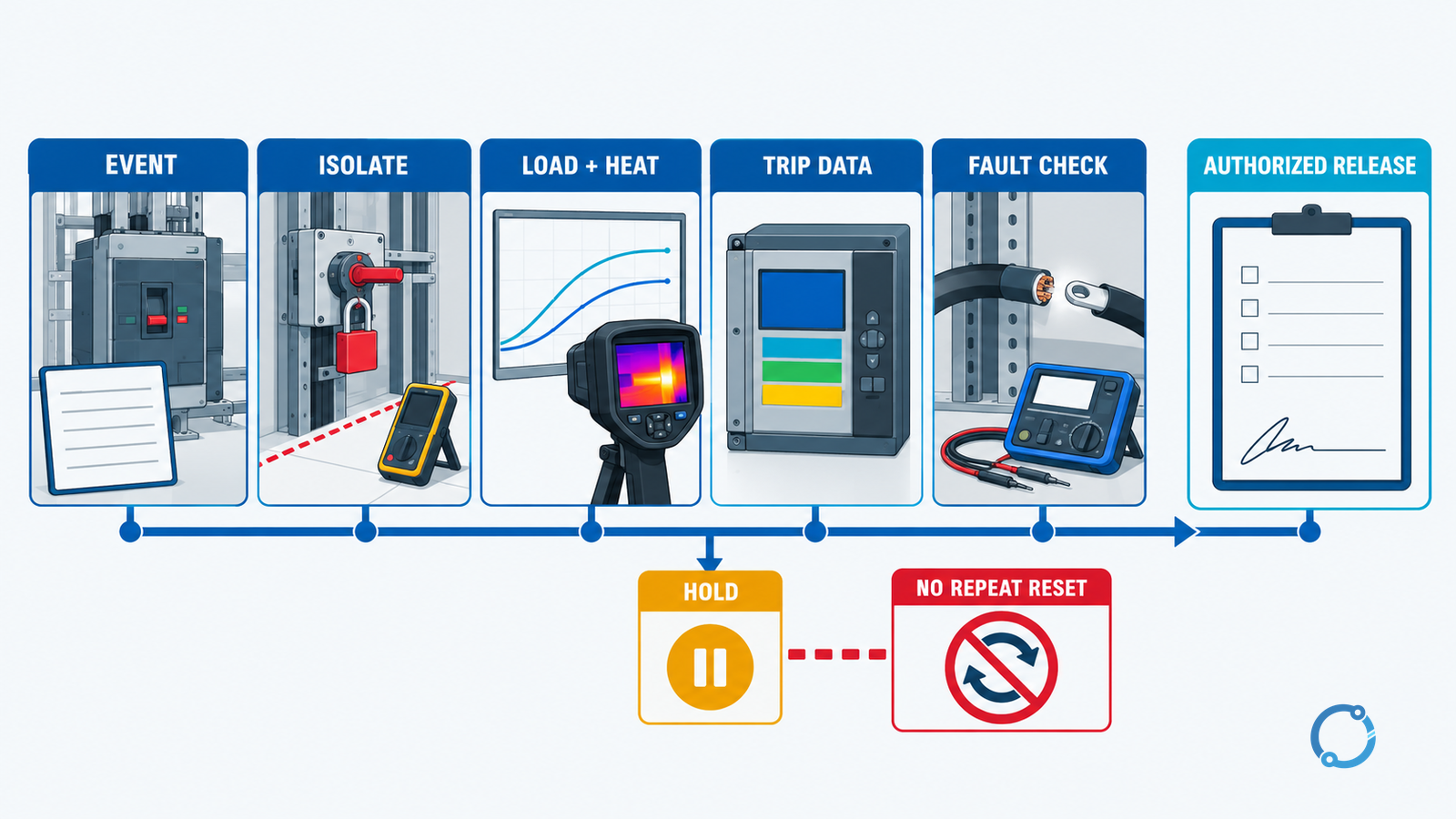
Controlled restoration is a planned test
If the responsible person authorizes a restoration, define the conditions in advance:
- who is responsible for the operation;
- which circuits and mechanical loads are enabled;
- what current, voltage, temperature and trip indication will be monitored;
- the duration and abort criteria;
- who can stop the test;
- what must be recorded;
- what constitutes a repeat trip.
Start with the minimum safe load and observe the event. A successful start after a cooling period does not prove the cause was thermal unless the operating record supports it. If the breaker trips again, stop. Do not keep increasing the load, changing the handle position or adjusting the trip unit to obtain a different result.
The low-voltage breaker selectivity guide explains why a trip may be correct even when it appears to affect more of the process than expected. Upstream and downstream devices must be checked as a coordination system, not only as individual components.
Fault versus trip-unit failure: a disciplined distinction
It is tempting to decide that an MCCB is defective when it trips repeatedly. Device failure is possible, but it should be the conclusion of evidence, not the default explanation. A protection device may appear to operate early because its ambient compensation, rating plug, waveform, load current or trip settings differ from the design. It may also carry mechanical or contact damage that a visual inspection cannot see.
Similarly, a trip unit that does not operate is not automatically the cause of an energized fault. A failed open device, a control power problem, an incorrect test condition or an arrangement that bypasses the intended sensing can create the same observation.
Record the comparison between:
- expected current and measured current;
- expected protection curve and actual device configuration;
- expected ambient and actual enclosure conditions;
- expected fault path and available fault current;
- expected control response and observed trip mechanism;
- product status and test result.
If the evidence is incomplete, label the hypothesis as unresolved. A replacement breaker installed without understanding the original trip may simply move the failure to a different place.
What to record after the investigation
A practical MCCB trip dossier should contain:
- Equipment identification and single-line location.
- Event time, load state and operator observations.
- Device rating, trip type and installed settings.
- All trip indications, flags, alarms and logs.
- Ambient, enclosure and thermal observations.
- Conductor, terminal and mechanical inspection results.
- Insulation, continuity or fault-location test results where applicable.
- Device test results and any manufacturer findings.
- Root-cause conclusion or unresolved hypothesis.
- Repair, setting change and protection-study update.
- Controlled restoration record.
- Post-restoration monitoring and sign-off.
The record is part of the safety case. It prevents a later operator from seeing a restored handle and assuming that the original condition was safely resolved.
The practical conclusion
Diagnose an MCCB trip from the event outward. Preserve the indication, identify the exact device and settings, compare the trip with real load and thermal conditions, retrieve electronic data where available, and test the circuit for fault conditions before considering restoration.
Do not treat a breaker handle as a reset switch for an unexplained electrical event. An overload, a thermal installation problem, a trip-unit setting issue and a short-circuit fault can all produce a trip, but they require different evidence and different corrective action. If the cause is unknown, repeated trips occur or any damage is present, keep the circuit isolated and escalate.