

Accept substation energy metering only after verifying the chain from primary conductors through instrument transformers and meter configuration to the reported energy register. Correct CT/VT ratios do not compensate for swapped phases, reversed direction or a multiplier applied twice. A meter accuracy certificate also does not prove the accuracy of the installed chain.
This workflow concerns transformer-operated metering in LV/MV substations, including operational energy monitoring. Revenue or settlement use adds the relevant utility, metrology and jurisdictional requirements. It is not a terminal-number wiring guide or authorization to work on energized secondary circuits.
Define the measurement that will be accepted
Begin with the one-line diagram and a written measurement boundary. Identify the feeder or incomer, its normal and alternate sources, and what “import” means at that boundary. A bus-coupler meter can legitimately report different direction when the source configuration changes. A negative register cannot be judged without the declared convention.
Identify the circuit arrangement expected by the meter: voltage inputs, current inputs, phase mapping and the applicable three-wire or four-wire measurement configuration. Assign each physical CT core and VT winding to a named channel. Use serial numbers and drawings, not only labels such as “metering CT.”
| Record field | Required meaning | Acceptance evidence |
|---|---|---|
| Measurement boundary | Which primary energy flow is counted | Approved one-line diagram and direction convention |
| Instrument-transformer channels | Phase, ratio, polarity, core/winding and purpose | Channel register and verified drawings |
| Meter configuration | Input circuit arrangement and scaling behavior | Saved configuration and relevant instructions |
| Reported quantities | Active/reactive energy, import/export and units | Register map with unambiguous definitions |
| Downstream data | Scaling, interval, timestamps and quality flags | Gateway/database mapping and test records |
For transformer selection inputs, use the separate CT selection criteria. This article begins where those choices become an installed measurement system.
Distinguish a type-tested meter from an accepted system
IEC 62052-11:2020 covers meter requirements and type tests, including external influences and common accuracy-test conditions. Its scope excludes several wider systems and functions. IEC 62053-22:2020 addresses transformer-operated static AC active-energy meters in specified accuracy classes and applies to their type tests.
Those scopes do not establish a universal installed-system error. Instrument-transformer ratio and phase errors, secondary loading, channel association and data processing all require their own assessment. Do not add class labels as if they were a guaranteed total error, or assume that a meter’s class covers the CTs, VTs and communications path.
Write the project’s acceptance tolerances, loading points and reference method before testing. NIST’s power and energy calibration guidance illustrates traceable measurement and measurement-assurance principles. It does not prescribe a single tolerance for every substation.
Prove where the CT/VT multiplier is applied
For conventional transformer-operated metering, a useful scaling check is:
K = (CT primary current / CT secondary current) × (VT primary voltage / VT secondary voltage)
Use corresponding voltage quantities on both sides. Do not mix a line-to-line primary value with a phase-to-neutral secondary value. If voltage is directly connected, its ratio contribution is one. The calculation does not describe every digital or low-power sensor interface.
Hypothetical example: a 400/5 A CT ratio gives 80. An 11,000/110 V VT ratio gives 100, using like-for-like voltages. The combined multiplier is 80 × 100 = 8,000. If a register genuinely reports secondary-side energy of 0.025 kWh, the corresponding primary energy is 0.025 × 8,000 = 200 kWh.
If the meter already reports 200 primary kWh, applying 8,000 again is wrong. Some meters apply ratios internally; some pulse outputs or separate registers use another documented basis. Verify each output independently. “The meter is configured with CT ratios” does not resolve every communications register or pulse constant.
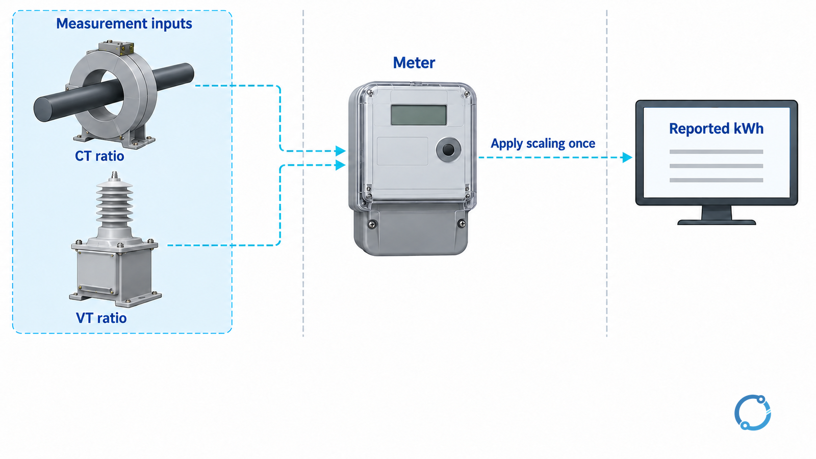
Create a scaling register with the raw quantity, raw unit, ratio basis, processing location and final unit. Check an actual record against this register. Never infer whether a Modbus value is scaled from its numerical size alone.
Use ordered commissioning gates
The following is an acceptance framework for qualified personnel under an approved test plan, not a live test recipe.
| Gate | What must be demonstrated | Hold condition |
|---|---|---|
| Safe test boundary | Every primary, auxiliary and secondary source is accounted for | The work could interrupt an energized CT secondary or expose an uncontrolled VT supply |
| Physical/channel verification | Phase association, polarity, core identity and test facilities match drawings | Any channel cannot be traced to its primary phase |
| Meter configuration | Circuit arrangement, ratios, register definitions and direction convention agree | Configuration and as-built schedule differ |
| Functional measurement | Approved reference checks confirm phase contribution and direction | Plausible total kWh masks an incorrect phase contribution |
| Output verification | Display, pulses and exported registers follow their declared scaling | Any output requires an unexplained multiplier |
| Data verification | Interval boundaries, time basis, units and quality status survive transfer | Missing or duplicate intervals are silently treated as valid energy |
| Restoration | Test positions, links, wiring, seals and configuration are recorded as left | Any temporary condition remains unresolved |
CT secondaries require special precautions. Never open one while primary current can flow. Use the CT installation and testing workflow for the component safety boundary and the approved shorting/test facilities. Voltage circuits have a different hazard: shorting a VT secondary is not the equivalent safe action. Do not copy CT test-link practice into a VT circuit.
In U.S. workplaces where applicable, OSHA 1910.333 governs de-energization and verification, including stored-energy precautions. Local procedures and competent-person requirements remain essential elsewhere.
Check pulses and intervals as separate interfaces
Read the pulse constant’s actual definition: pulses per kWh and kWh per pulse are reciprocals, not interchangeable labels. Confirm whether its energy basis is primary or secondary. Compare an approved test interval’s pulse count with the corresponding meter-register change, allowing for pulse resolution and the written tolerance.
For logged data, distinguish cumulative energy from interval energy and average power. Confirm interval duration, timestamp convention, clock synchronization and treatment of resets or rollovers. A graph that looks reasonable can still contain duplicated scaling or a time-boundary error.
Do not force incoming and outgoing feeder totals to match exactly. They may cover different time boundaries or omit transformer and auxiliary losses. An energy balance is a diagnostic check whose physical boundary must be declared, not a substitute for traceable commissioning.
Release a reproducible record
Retain the channel register, configuration files, ratio calculations, reference-instrument traceability, results and tolerances, output maps and as-left restoration record. Assign responsibility for reviewing changes to CT taps, VT ratios, replacement meters and gateway configuration.
For directly connected single-phase installations, use the separate single-phase meter installation guide. Substation acceptance requires the wider transformer-to-data chain described here.