
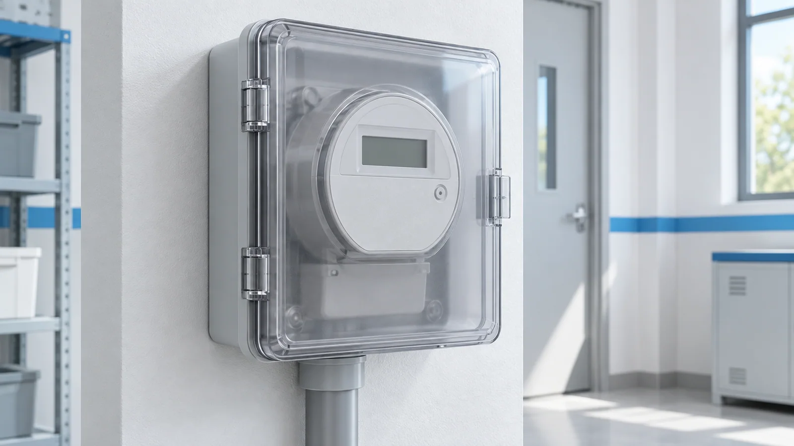
There is no universal terminal-number diagram for a single-phase kilowatt-hour (kWh) meter. Before installation, identify whether the meter is directly connected or transformer operated, obtain the exact device and socket wiring diagram, confirm who owns and may open the service equipment, and match line, load, neutral and protective-earth arrangements to the local design. Qualified personnel then isolate all sources, verify absence of voltage, wire only to the approved diagram, and complete documented checks before energization.
This article is an engineering workflow for low-voltage single-phase metering, especially submetering inside an authorized installation. Utility revenue meters, sealed sockets and service conductors often have separate ownership and procedures. Do not break a seal or work on service equipment without the utility or authority’s permission.
Decide the meter topology before reading terminal numbers
| Question | Directly connected meter | Transformer-operated meter |
|---|---|---|
| How is current measured? | Load current passes through meter’s rated current path | Current transformer or other specified sensor provides a measured signal |
| Main wiring concern | Correct source/load path and terminal rating | Correct sensor ratio, polarity, secondary circuit and compatible meter input |
| Critical boundary | Meter and terminals must suit feeder current and fault environment | Never improvise on a current-transformer secondary; use approved isolation and test procedures |
This guide focuses on the direct-connected case. If the meter uses a current transformer, stop and use its exact scheme and the current-transformer installation and testing guide with qualified review. A direct-connected diagram cannot be repurposed for a transformer-operated meter.
Build the installation packet
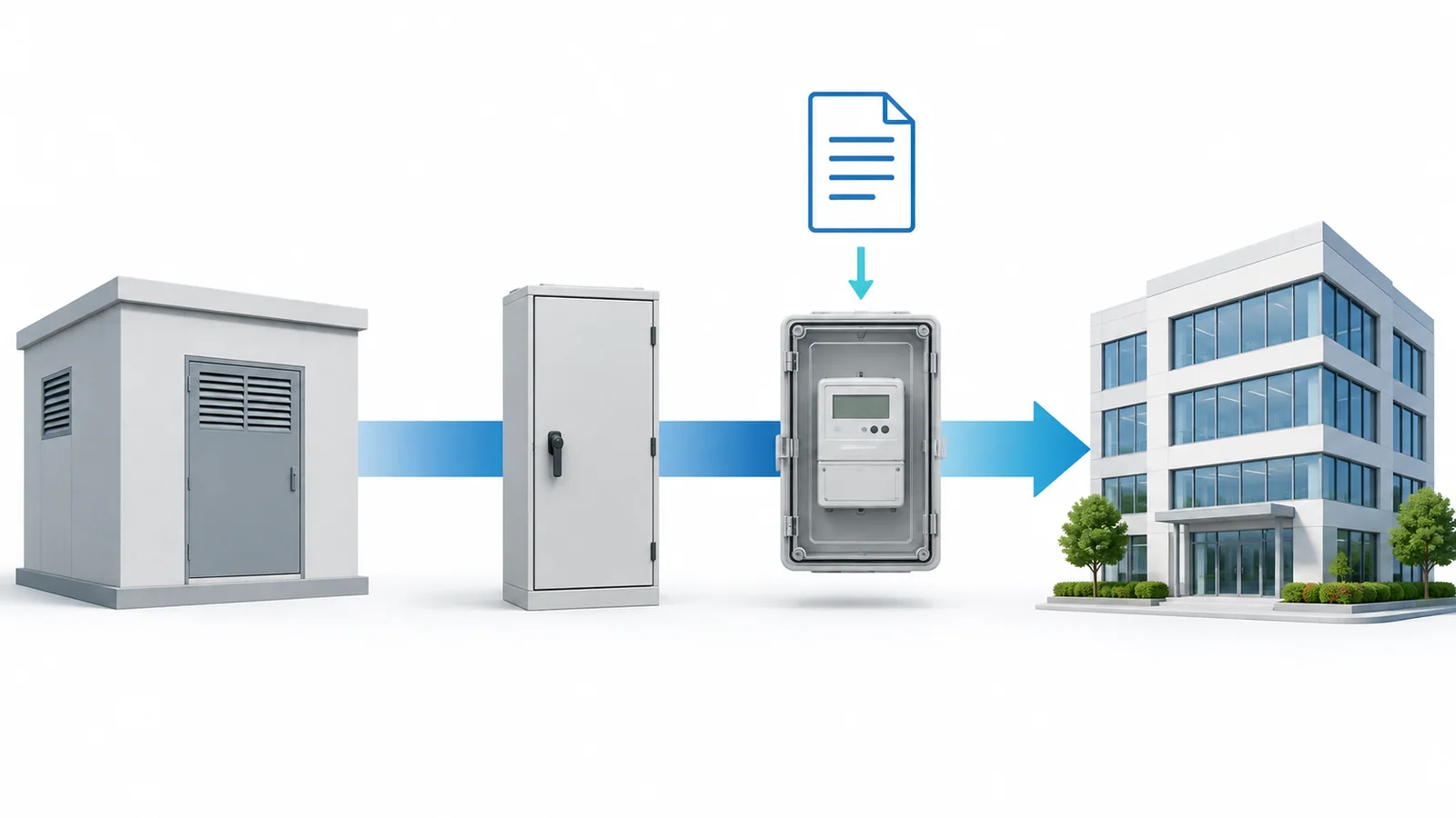
Collect the meter make and complete model, approved socket or mounting arrangement, wiring and terminal diagram, rated voltage/frequency/current, conductor acceptance, torque or tool requirements, overcurrent and disconnecting arrangements, enclosure rating, and applicable approval evidence. Confirm whether the meter is for billing, private allocation or monitoring; legal metrology and utility rules vary by location and use.
IEC 62052-11:2020 covers general requirements and type tests for electricity metering equipment, including functional, electrical and marking requirements within its scope. IEC 62053-21:2020 covers particular accuracy requirements for specified static AC active-energy meters. IEC 62052-31:2024 addresses product safety tests; its scope explicitly assumes skilled persons for installation and maintenance. None of these catalog descriptions is a substitute for the exact meter instructions or local approval.
For U.S. non-utility submetering, NIST’s current Handbook 44 page distinguishes the tentative code for non-utility electricity-measuring systems. Verify local adoption and the intended billing use rather than assuming every submeter is a utility revenue meter.
Four hold points before energization
Gate 1: authority and isolation
Identify the owner of the meter, socket, seals and service side. Obtain the required outage and access authorization. Map normal, standby, photovoltaic, storage and other possible backfeed sources. The work should follow the site’s isolation and lockout procedure; a switch position or dark display is not proof of de-energization.
For exposed fixed electrical equipment in U.S. general industry, OSHA 1910.333 requires a qualified person to test the circuit elements and parts to which workers will be exposed and verify that they are de-energized. The exact procedure, instrument and personal protective equipment depend on the installation and jurisdiction.
Gate 2: schematic and conductors
Match the actual supply system to the meter diagram: voltage, frequency, source and load orientation, neutral arrangement, permitted protective-earth routing, and any auxiliary supply or communications terminals. Do not copy terminal numbering from another meter, even when the case looks identical.
Verify conductor material, cross-section, insulation rating, temperature, number of wires per terminal and preparation. The breaker-feeder cable sizing guide covers conductor and protective-device coordination; the meter terminal still has its own acceptance limits. Confirm that the chosen socket and enclosure allow required bends, sealing and covers.
Gate 3: assembly and inspection
Under the approved safe-work condition, mount the device and make connections according to the exact scheme and torque/tool instructions. Support conductors so terminals do not carry cable strain. Preserve separators, shutters, terminal covers and environmental seals. Keep the protective-earth continuity path independent of measurement electronics unless the design and product explicitly require otherwise.
An independent inspection should compare every terminal against the actual drawing, look for trapped insulation or exposed strands, confirm source/load orientation and neutral treatment, and confirm the correct protective device and disconnecting method. Do not infer a safe installation from a power-on display.
Gate 4: approved tests and handover
Perform the project and utility’s required tests in the specified sequence. These may include continuity, polarity or source/load checks, insulation tests with sensitive electronics disconnected as needed, and a controlled functional check. Do not apply an insulation-resistance test through the meter unless the device and approved test plan permit it; see the insulation-resistance testing guide.
At handover, record the installed model and serial number, wiring diagram revision, protective device, test results, sealing or custody status, initial reading, and who accepted the work. A test pulse or increasing register can indicate operation but does not by itself prove accuracy, correct tariff configuration or legal suitability for billing.
Common errors and stop conditions
| Finding | Why it matters | Safe next action |
|---|---|---|
| Terminal numbers differ from a web diagram | Numbering is product-specific | Use the exact manufacturer’s approved scheme |
| Meter is direct-connected but feeder exceeds its specified current path | Heating and rating mismatch | Redesign with a suitable meter or approved sensor topology |
| Unclear neutral or multiple supply sources | Miswiring or backfeed risk | Resolve system schematic and isolation boundary |
| Utility seal or socket ownership is unclear | Unauthorized access and unsafe service work | Stop and obtain owner/utility direction |
| Display is active but readings are suspect | Operation is not accuracy verification | Use the authorized test procedure and configuration record |
A useful installation guide names the required decisions and inspections, but it cannot safely publish one generic set of live conductor-to-terminal instructions for every meter. The device documentation and local authority resolve that last, product-specific step.