
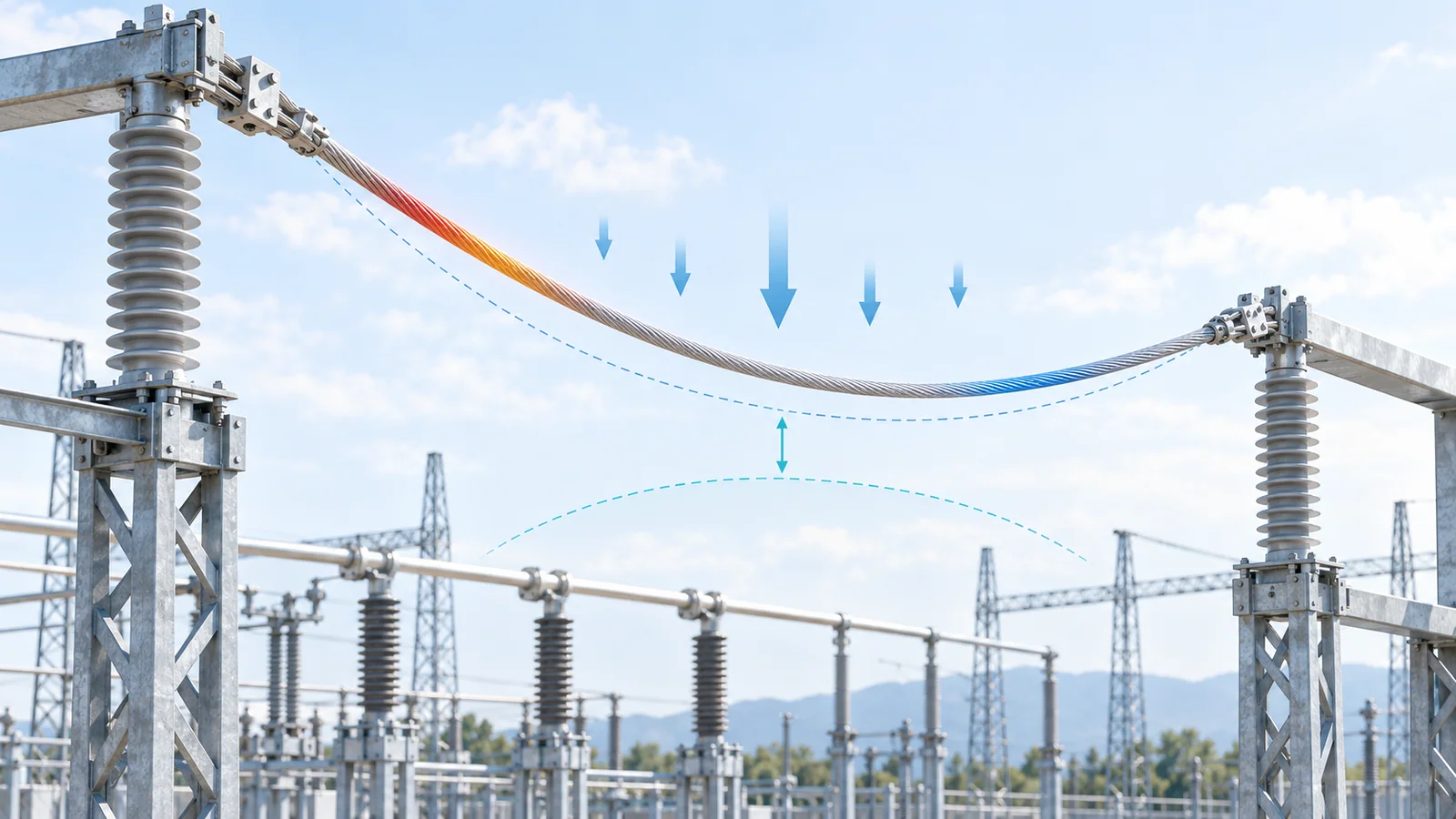
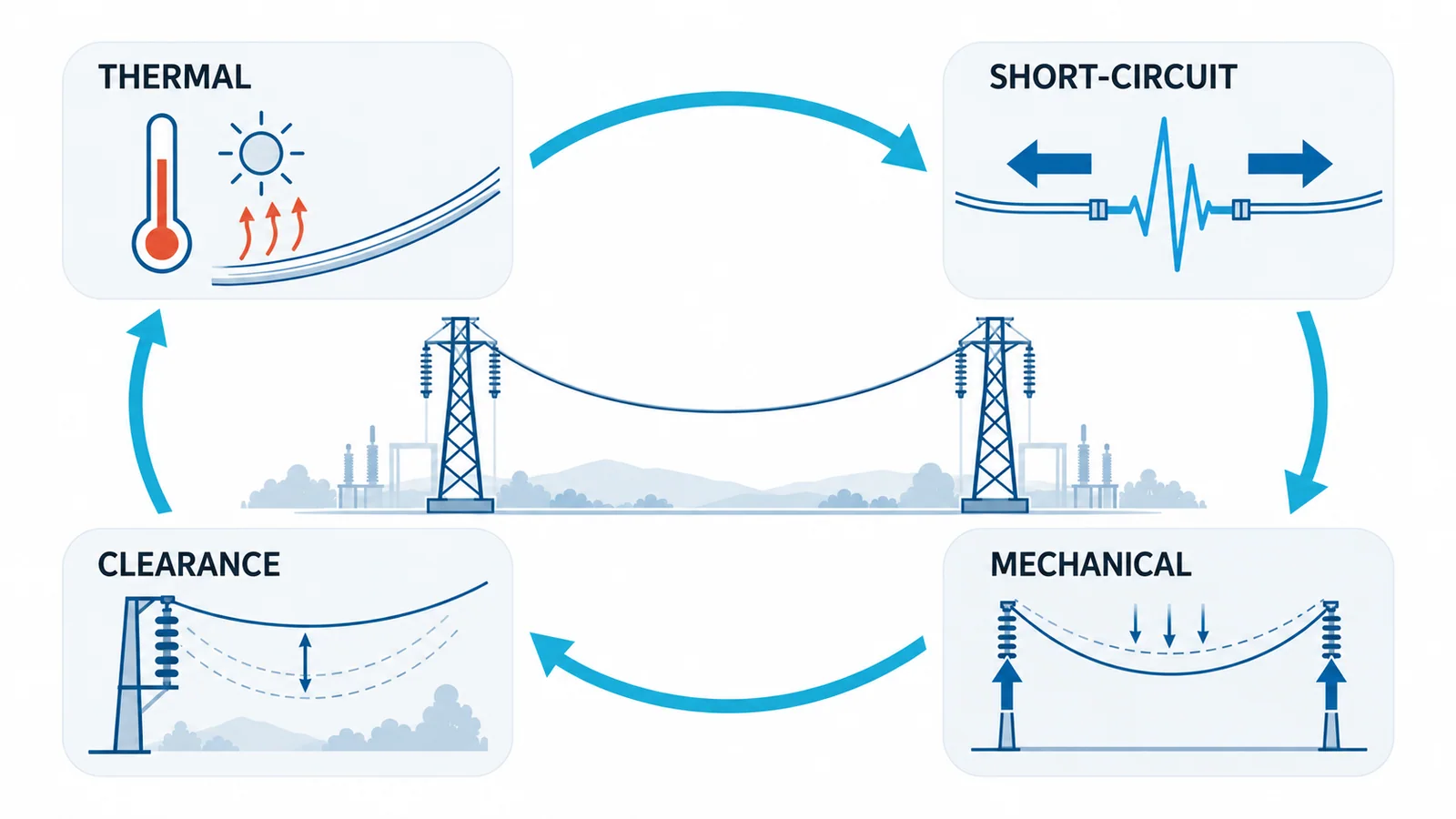
Selecting a flexible bare conductor for an outdoor substation is not an ampacity lookup. The selected conductor, bundle, span and fittings must pass four linked studies: continuous and emergency thermal performance; short-circuit thermal and electrodynamic duty; mechanical sag, tension and loading; and electrical clearance, corona and insulation coordination. Use one controlled input set across all four, then iterate until the same physical arrangement passes every acceptance criterion.
This article addresses flexible strain-bus conductors and short flexible equipment connections within a substation. It does not replace a transmission-line design, rigid-bus calculation, structure design, utility standard or site-specific insulation-coordination study.
The four-study decision matrix
| Study | Governing inputs | Primary outputs | Typical design change when it fails |
|---|---|---|---|
| thermal rating | load cases, conductor properties, maximum conductor temperature, weather assumptions, solar heating | steady-state and transient current capability, operating temperature | larger conductor, bundle, lower terminal temperature, revised load limit |
| short-circuit effects | initial symmetrical current, peak current, fault duration, reclosing sequence, span geometry | temperature rise, tensile force, conductor displacement, fitting/structure loads | larger conductor, shorter span, more separation, stronger support/fittings |
| mechanical behavior | span, initial tension, conductor mass, temperature range, wind/ice/seismic loads, support elevations | sag, final tension, support reactions, fatigue/vibration controls | revise tension, span, support position, conductor or damping |
| electrical integration | highest voltage for equipment, overvoltage study, withstand levels, conductor diameter/bundle, site altitude/pollution | required clearances, corona/RIV screening, terminal and insulator requirements | increase spacing, change bundle/diameter, revise insulation or layout |
The studies share inputs. A higher allowable conductor temperature may improve ampacity but increase sag. A larger bundle may reduce electric-field stress yet raise wind load and short-circuit force. Treat the result as a convergence problem, not four independent approvals.
Build one design basis before calculating
Start with a controlled data sheet:
- system nominal voltage and highest voltage for equipment;
- normal, contingency and emergency current cases with duration;
- prospective short-circuit current, peak current, duration and reclosing duty;
- conductor material, construction, diameter, mass, DC resistance and temperature coefficients;
- span length, phase arrangement, bundle spacing and support elevations;
- terminal, clamp and equipment allowable loads and temperatures;
- minimum and maximum ambient temperature, solar input, wind and icing assumptions;
- altitude, pollution, salt or industrial contamination and site exposure;
- required insulation withstand levels and operating clearances;
- local utility, structural, seismic and environmental criteria.
Record the source and revision for every consequential input. A conductor study cannot compensate for an optimistic fault-clearing time, inconsistent weather case or missing terminal limit.
Study 1: continuous and emergency thermal rating
For a bare conductor, current raises temperature through electrical losses, while convection and radiation remove heat and solar radiation may add heat. In simplified steady state:
I²R(Tc) + Qsolar = Qconv + Qrad
where:
- I is conductor current, A;
- R(Tc) is AC resistance at conductor temperature, Ω per unit length;
- Tc is conductor temperature;
- Qsolar, Qconv and Qrad are heat rates per unit length.
IEEE 738-2023 provides a numerical method relating bare-overhead-conductor current, temperature and weather. The standard explicitly does not choose the appropriate weather or conductor assumptions for the user. For a substation, those assumptions must also reflect short spans, nearby equipment, terminal heating and the applicable utility practice.
Check at least:
- normal continuous loading;
- credible contingency loading;
- time-limited emergency loading, if the operating philosophy allows it;
- terminal and connector temperature limits;
- transient heating and cooling where the load duration is shorter than thermal stabilization.
Do not transfer a transmission-line ampacity directly into a substation schedule. Clamps, jumpers, bundled geometry, low wind at equipment level and adjacent heat sources can change the limiting component.
Study 2: short-circuit thermal and electrodynamic duty
A fault creates two different checks.
Thermal withstand
An adiabatic screening relation is often written as:
Ith = kA / √t
or equivalently A = Ith√t / k, where A is conductor area, t is fault duration and k depends on material and permissible initial/final temperatures. The project method must define the applicable material properties and whether heat transfer can be neglected. A screening result is not a substitute for the selected standard’s full method.
Electrodynamic force and displacement
The peak current produces electromagnetic force between phases. In flexible conductors, the important outputs include tensile force, support load, swing and minimum dynamic separation. IEC 60865-1:2011 includes calculation procedures for electromagnetic effects on rigid and flexible conductors and thermal effects on bare conductors.
Use the actual geometry, peak factor, fault type, fault duration and support flexibility. Verify:
- conductor-to-conductor and conductor-to-earth separation during maximum swing;
- insulator, clamp, terminal and structure loads;
- dropper and equipment-connection forces;
- effects of automatic reclosing when applicable;
- clearance after permanent elongation or fitting movement.
This study often governs span length and support loads even when the conductor easily passes continuous ampacity.
Study 3: sag, tension and environmental loading
The conductor must maintain clearances and acceptable support reactions across its temperature and load envelope. A parabolic screening approximation for level supports is:
s ≈ wL² / (8H)
where s is midspan sag, w is resultant load per unit length, L is span and H is the horizontal tension component. This relation is useful for sensitivity checks, but final design should use the project’s accepted sag-tension model, conductor stress-strain data and unequal-support geometry where relevant.
Consider:
- hot, still-air condition associated with maximum conductor temperature;
- cold condition and maximum tension;
- wind and ice combinations defined by local criteria;
- construction tension and long-term creep;
- aeolian vibration, subspan oscillation or galloping where credible;
- seismic movement and equipment-terminal displacement where required;
- tolerances in support position and conductor length.
IEC 60826:2017 provides reliability-based loading and strength concepts for overhead lines. It does not provide detailed substation-component design, so use it only where adopted by the project together with substation and structural requirements.
Study 4: clearances, corona and insulation coordination
The conductor layout must withstand the expected electrical stresses while maintaining operational and maintenance clearances. IEC 60071-1:2019 establishes principles for selecting rated withstand voltages in AC systems above 1 kV. Human-safety clearances and work practices are separate requirements.
The study should connect:
- highest voltage for equipment;
- temporary, switching and lightning overvoltage results;
- selected withstand levels;
- altitude and atmospheric correction where applicable;
- phase-to-earth, phase-to-phase and longitudinal clearances;
- conductor diameter and bundle geometry;
- maximum static sag and fault displacement;
- insulator length, hardware and terminal geometry;
- corona, radio interference or audible-noise criteria where specified.
Corona performance is not determined by nominal voltage alone. Surface electric stress depends on conductor radius, bundle arrangement, phase spacing, surface condition and atmospheric conditions. Use the utility’s accepted method or an electric-field study for critical projects rather than relying on a generic diameter rule.
A bounded screening example
Assume a candidate conductor in a 20 m level span has a resultant vertical load of 1.2 kg/m under one screening condition. Convert mass per length to force:
w = 1.2 × 9.81 = 11.77 N/m
If the horizontal tension component is 20 kN, the parabolic estimate is:
s ≈ 11.77 × 20² / (8 × 20,000) = 0.029 m
The estimated sag is about 29 mm for that one load and tension state. It does not establish final clearance because the hot-state tension, wind load, support elevation, creep and fault displacement remain untested. Its value is diagnostic: if a layout has only a few millimetres of margin, the design is not robust enough to proceed on a simplified estimate.
How to converge on a selection
Use this sequence:
- screen conductor families against continuous current and terminal compatibility;
- establish geometry and span arrangement;
- calculate hot-state sag and cold/load-case tension;
- run short-circuit force, displacement and thermal checks;
- verify insulation coordination and clearances in normal and displaced states;
- check corona/environmental criteria where required;
- update structures, fittings and equipment terminal loads;
- repeat until the same configuration passes all cases;
- capture governing cases and margins in the specification.
For a wider station context, see distribution substation fundamentals. Where the alternative is rigid copper, the busbar ampacity and derating guide explains why temperature-rise evidence still controls the final rating.
Specification and review checklist
The issued conductor schedule should identify:
- conductor standard, material, construction, area and diameter;
- bundle count and spacing;
- span, phase spacing and installation tension;
- normal/emergency current and allowable duration;
- maximum design conductor temperature;
- short-circuit current, peak, duration and reclosing basis;
- calculated support, clamp and equipment-terminal loads;
- minimum normal and fault-displaced clearances;
- insulator and fitting interfaces;
- environmental and corrosion requirements;
- required type/routine documentation and field inspection;
- assumptions that operations must preserve.
Stop the design review if load forecasts, fault duty, clearing time, terminal limits, weather data or insulation levels are unresolved. Those are selection inputs, not details to be filled in after purchase.
Safety boundary
Substation conductor design and installation require qualified electrical, structural and protection personnel. Construction and maintenance must follow the site’s isolation, lockout/tagout, absence-of-voltage verification, grounding and induced-voltage controls. This article does not specify approach distances, live-working methods or temporary grounding design.