
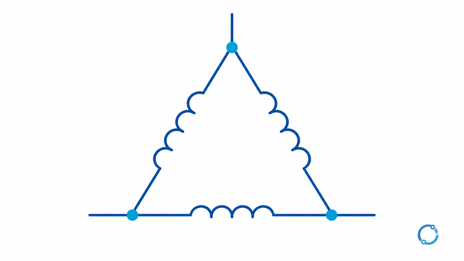
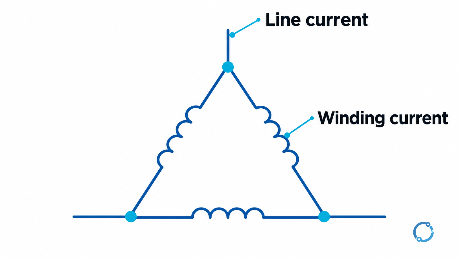
For a balanced, sinusoidal delta-connected transformer winding, line-to-line voltage equals winding voltage, while line current equals √3 times winding current. Apply the turns ratio to corresponding winding voltages, not automatically to the two line-to-line voltages of a delta–wye transformer.
Keep three labels on every value: the transformer side, line or winding basis, and unit. Those labels prevent most misplaced √3 factors before a calculator is used. The relationships below concern steady-state root-mean-square (RMS) magnitudes and an ideal transformer model where stated. They do not calculate protection settings, an open-delta bank rating, unbalanced loading or a reconnection procedure.
Put the line and winding quantities on separate rows
Here, VLL is voltage between two line conductors; Vw is voltage across one phase winding; IL is current in one external line; and Iw is current through one phase winding. “Phase voltage” means winding voltage in this article, not universally line-to-neutral voltage.
| Quantity | Delta side | Wye side, for comparison |
|---|---|---|
| Winding voltage | Vw = VLL | Vw = VLL ÷ √3 |
| Winding current | Iw = IL ÷ √3 | Iw = IL |
| Total apparent power | S = √3 × VLL × IL = 3 × Vw × Iw | Same total-power expressions under the balanced model |
| Corresponding winding-voltage ratio | a = Vw1 ÷ Vw2 | Use the actual connection on each side before calculating a |
Use volts and amperes to obtain volt-amperes (VA), or divide by 1,000 for kilovolt-amperes (kVA). The subscripts 1 and 2 identify primary and secondary. The ratio a represents N1/N2, the corresponding winding turns ratio, under the ideal model.
The U.S. Department of Energy’s Electrical Science handbook, Volume 3, module ES-09, gives the balanced delta/wye line relationships. Volume 4, module ES-13, treats transformer turns ratios and connection combinations. These are historical fundamentals references, not newly issued 2026 standards despite their current hosting paths.
Why delta line current is not winding current
At a delta corner, the external line current is the phasor difference of two winding currents. Under the balanced sinusoidal conditions, that difference has magnitude √3 × Iw. Adding the two current magnitudes arithmetically would give the wrong result because their phase relationship matters.
Each delta winding is connected between two line nodes, which is why its voltage magnitude is VLL. There is no general delta neutral voltage obtained by dividing this winding voltage by √3. If a particular system includes a tapped winding or grounding arrangement, identify it explicitly rather than inventing a neutral in the basic triangle.
Magnitude conversion also does not settle the phase displacement across a transformer. Use the actual vector group, polarity and phase sequence for angle-sensitive work. The dedicated transformer differential-relay guide addresses protection compensation rather than this basic magnitude calculation.
Worked example: 300 kVA delta–delta transformer
Assume a hypothetical ideal transformer carrying balanced rated apparent power of 300 kVA, with 11 kV primary line-to-line and 400 V secondary line-to-line, both windings delta connected. Ignore losses, excitation current and voltage regulation for this educational calculation. The numbers are not a product rating or measured operating record.
Calculate each line current using the same total three-phase apparent power:
IL = S ÷ (√3 × VLL)
- Primary: 300,000 ÷ (√3 × 11,000) = 15.75 A, approximately.
- Secondary: 300,000 ÷ (√3 × 400) = 433.01 A, approximately.
Then convert each delta line current to winding current:
- Primary winding: 15.7459 ÷ √3 = 9.09 A.
- Secondary winding: 433.0127 ÷ √3 = 250 A.
The winding voltages are 11,000 V and 400 V, so the ideal turns ratio is:
a = 11,000 ÷ 400 = 27.5
As a cross-check, the ideal inverse current relationship applies to the corresponding windings: Iw2/Iw1 = 250/9.0909 ≈ 27.5. Independently, the secondary winding calculation gives 3 × 400 × 250 = 300,000 VA, agreeing with √3 × VLL × IL before rounding.
Do not multiply this three-phase 300 kVA figure by three again. The calculation already represents all three phases.
Change the connection and the line-voltage ratio changes
Now consider a different hypothetical design: retain the 11,000/400 V winding-voltage ratio but connect the secondary windings in wye. Each secondary winding still has 400 V under the ideal assumptions, but the secondary line voltage becomes:
VLL2 = √3 × 400 = 692.82 V
At 300 kVA, secondary line current would be 250 A, equal to its winding current. The line-voltage ratio is about 15.88, while the winding turns ratio remains 27.5. They are different quantities.
If the design instead requires 400 V line-to-line on a wye secondary, each secondary winding needs 400/√3 = 230.94 V under the model. The corresponding primary-delta-to-secondary-wye winding ratio is then 11,000/230.9401 ≈ 47.63, not 27.5.
These comparisons explain the calculation; they do not authorize reconnecting an existing transformer. Available terminals, winding construction, insulation, ratings and the approved nameplate arrangement determine whether any change is permitted.
Use apparent power and real power consistently
The previous example used kVA. For balanced sinusoidal conditions with power factor cosφ, real power is P = √3 × VLL × IL × cosφ. If a load is given in kW rather than kVA, its current calculation also needs the appropriate power factor. Do not insert kW into the kVA formula and silently assume unity power factor.
Transformer losses and excitation mean actual input and output quantities will not follow an ideal equality exactly. Unbalance, harmonics, regulation and tap position can also invalidate a simplified calculation or change the required interpretation. State these limitations rather than forcing every measured phase into one averaged √3 conversion.
Before releasing a worksheet, check units, side, connection, line/winding basis, total versus per-phase power, ratio definition and rounding. Then compare the result with the actual equipment specification. The IEC 60076 specification guide covers that broader equipment-evidence task; this calculation alone does not establish thermal capacity, fault duty or compliance.