
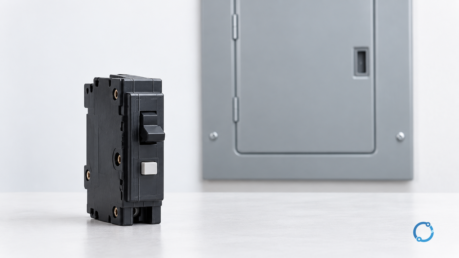
An AFCI breaker installation should be accepted only after the breaker is verified for the actual panel and circuit, its neutral arrangement follows the exact device instructions, and the specified installation and functional checks pass. Physical fit, a successful reset or a photograph of another panel is not enough.
The reliable workflow is identify → verify compatibility → resolve circuit conductors → install under controlled isolation → test and record. This guide addresses U.S. branch-circuit installation review by qualified personnel. It is not a generic terminal-by-terminal wiring diagram or a do-it-yourself panel-work procedure.
Confirm what protection the circuit needs
An arc-fault circuit interrupter (AFCI) and a ground-fault circuit interrupter (GFCI) serve different protective functions. Confirm the locally adopted National Electrical Code (NEC), amendments, circuit and occupancy before selecting a device. A “combination-type AFCI” designation must not be read as a promise of both AFCI and personnel GFCI protection; use the actual device identification.
The existing GFCI and AFCI comparison owns that hazard distinction. This article begins at installation acceptance: does the selected protection work with the identified panel, conductor arrangement and instructions?
Record the full panel identification, breaker designation, poles, voltage, current rating, interrupting suitability, circuit description and relevant instructions. Current rating is only one selection input. The separate circuit-breaker sizing guide explains why the load alone does not establish a complete breaker specification.
Gate 1: prove the panel–breaker combination
Use the panel markings and applicable evaluated combination, including any classification conditions, to establish suitability. Two breakers that occupy the same slot are not therefore interchangeable.
UL’s Panelboard Application Guide treats field-installed equipment and the identified assembly as application checks. Its circuit-breaker marking and application guide addresses breaker markings, terminals and installation instructions. These are evidence routes, not approval of an unnamed replacement.
Check the exact combination rather than relying on a brand family. Verify any limitations attached to the panel position, accessory, voltage, poles or installation arrangement. Keep a readable record of the evidence used. If the actual panel cannot be identified or the proposed combination is unsupported, hold the installation.
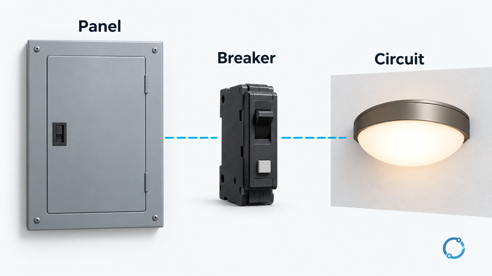
Gate 2: resolve the exact neutral arrangement
Do not convert “AFCI breaker” into one universal wiring rule. The supply-neutral interface and the required branch-neutral termination depend on the actual device and panel system. A plug-on-neutral design does not justify guessing where the branch neutral belongs.
Use this decision table before conductor work starts:
| Observed arrangement | Evidence to obtain | Stop or hold condition |
|---|---|---|
| Device with a supply-neutral lead | Exact lead purpose and terminal routing from its instructions | Lead identity or permitted panel connection is uncertain |
| Plug-on-neutral device | Compatible panel interface and the device’s branch-neutral instructions | Mechanical engagement or neutral routing is inferred from appearance |
| Branch circuit with its own identified neutral | Conductor identity and the required route for this breaker | Neutral belongs to another circuit or cannot be traced |
| Shared-neutral or multiwire branch circuit | Approved circuit arrangement, required disconnecting/protective configuration and suitable device | A one-pole substitution is proposed without resolving the complete arrangement |
| Existing downstream neutral-to-ground connection | Qualified investigation against the permitted system arrangement | An unintended connection remains unexplained |
This table does not prescribe terminals, conductor colors or a compatible model. It identifies questions the exact installation documents must answer. Protective grounding must remain distinct from neutral routing; do not substitute one for the other to obtain a reset.
Where several ungrounded conductors share a circuit relationship, use the neutral switching and linked-pole guide for the separate system question. A handle arrangement alone does not establish all AFCI sensing or listing conditions.
Gate 3: establish the work boundary before installation
Panel work can expose parts that remain live after a main breaker opens. Confirm every relevant source and any backfeed with the responsible qualified team. Do not remove covers, move conductors or insert a breaker as an informal diagnostic experiment.
For covered U.S. general-industry work, the Occupational Safety and Health Administration (OSHA) rule 29 CFR 1910.333 requires the applicable deenergization, lockout/tagout and qualified verification process. Personal protective equipment and any exceptional energized activity must be resolved through the governing safety program, not inferred from this article.
Under the approved installation method, verify conductor material and permitted size, stripping and termination requirements, terminal occupancy, specified tightening method, device seating and enclosure restoration. Use the actual instructions and suitable tools. No universal torque value follows from the AFCI designation.
If existing conductors are damaged, unidentified or unsuitable for the terminal, stop and resolve the defect. Do not trim strands, double up a terminal without permission, or increase the breaker rating to work around an installation problem.
Gate 4: distinguish inspection from functional testing
Inspect the installation against the accepted documents before the authorized energization and functional test. Retain the conductor/circuit identification, installation checks and as-left enclosure condition.
UL’s circuit-breaker guide describes the AFCI’s marked test function as a simulated arc-detection check. Perform the exact manufacturer’s test and reset sequence under the approved procedure. A successful test does not separately prove every downstream termination, conductor identity or grounding connection.
Do not create intentional arcs, short conductors or introduce improvised faults to prove protection. External test equipment, where appropriate, must be selected and interpreted for the actual device and test objective; an unexplained indication is not grounds to defeat the protection.
If the breaker will not reset or repeatedly trips, retain its indication and the operating circumstances. Determine whether the issue is installation, circuit condition, connected equipment or the protective device. Do not remove AFCI protection merely to obtain uninterrupted service.
Hand over an installation acceptance record
The record should connect the panel and breaker identity to compatibility evidence, adopted requirement, circuit/neutral arrangement, installation inspection and specified functional-test result. Include unresolved findings, corrective actions, instructions for the user and the responsible sign-off.
A hypothetical replacement with a new neutral interface illustrates the completion test: the reviewer must be able to find the new device’s circuit-neutral instructions and the panel’s compatibility evidence. “The old breaker had a white lead” is not an adequate basis for the new installation.
Acceptance is complete when the actual arrangement and required tests are documented without unresolved compatibility, routing or safety issues. A breaker that fits and stays on has not, by those observations alone, passed that review.