
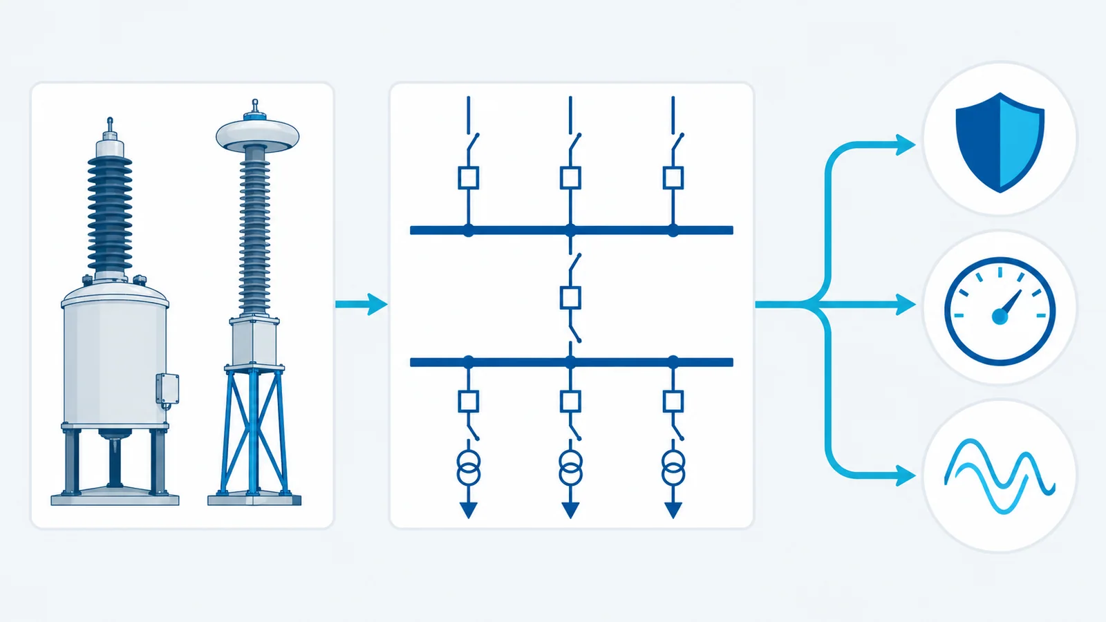
In a complex substation, select the voltage-transformer (VT) scheme from the functions and switching topology before selecting a device. Map every protection, metering, synchronism, control and automation function to a normal voltage source, an allowed alternative source, a failure alarm and a test boundary. Then specify VT technology, primary ratio, insulation level, secondary windings, accuracy, burden, grounding, protection and transfer logic.
A technically adequate VT can still produce an unreliable scheme if its location becomes de-energized during a valid bus configuration or if automatic transfer mixes unsynchronized voltage sources.
Define the system boundary
This guide covers instrument-voltage sources for AC substations above 1 kV, especially double-bus, transfer-bus and breaker-and-a-half arrangements. It focuses on conventional inductive voltage transformers (IVTs), capacitor voltage transformers (CVTs) and the scheme around them. Digital-output instrument transformers and non-conventional sensors require additional interface and time-synchronization analysis.
IEC 61869-1:2023 gives general requirements for instrument transformers above 1 kV AC or 1.5 kV DC, including analogue or digital secondary signals. Device-specific requirements are addressed in the relevant parts of the series.
Step 1: inventory every voltage-dependent function
Do not begin with “three VTs per bus.” Begin with the functions:
- revenue and operational metering;
- distance protection and directional elements;
- over/undervoltage and frequency protection;
- synchronism check and synchronizing;
- automatic transfer and reclosing supervision;
- transformer V/Hz protection;
- power-quality monitoring;
- SCADA indication and sequence-of-events records;
- line-carrier coupling, where a CVT/CVT stack serves that purpose;
- bus-dead/line-dead logic;
- disturbance recording and phasor measurement.
For each function, record required phases, residual voltage, accuracy, bandwidth/transient needs, burden, redundancy and behavior when the source is lost.
Step 2: build a voltage-source availability matrix
List all valid switching states, not just the normal one.
| Function | Normal source | Valid alternate | Source-selection condition | Failure response |
|---|---|---|---|---|
| bus metering | VT on energized bus section | coupled bus VT if approved | bus-coupler and isolator status proven | alarm and quality flag |
| line distance | line VT/CVT | normally none unless engineered | line-side source available | block/modify affected elements per study |
| synchronism check | voltages on both sides of open breaker | no arbitrary substitution | breaker and disconnect topology verified | inhibit close and alarm |
| transformer V/Hz | winding-associated bus VT | approved redundant bus source | transformer connected to that bus | alarm/block per protection design |
| SCADA bus voltage | selected bus VT | redundant channel where provided | source validity logic | bad-quality indication |
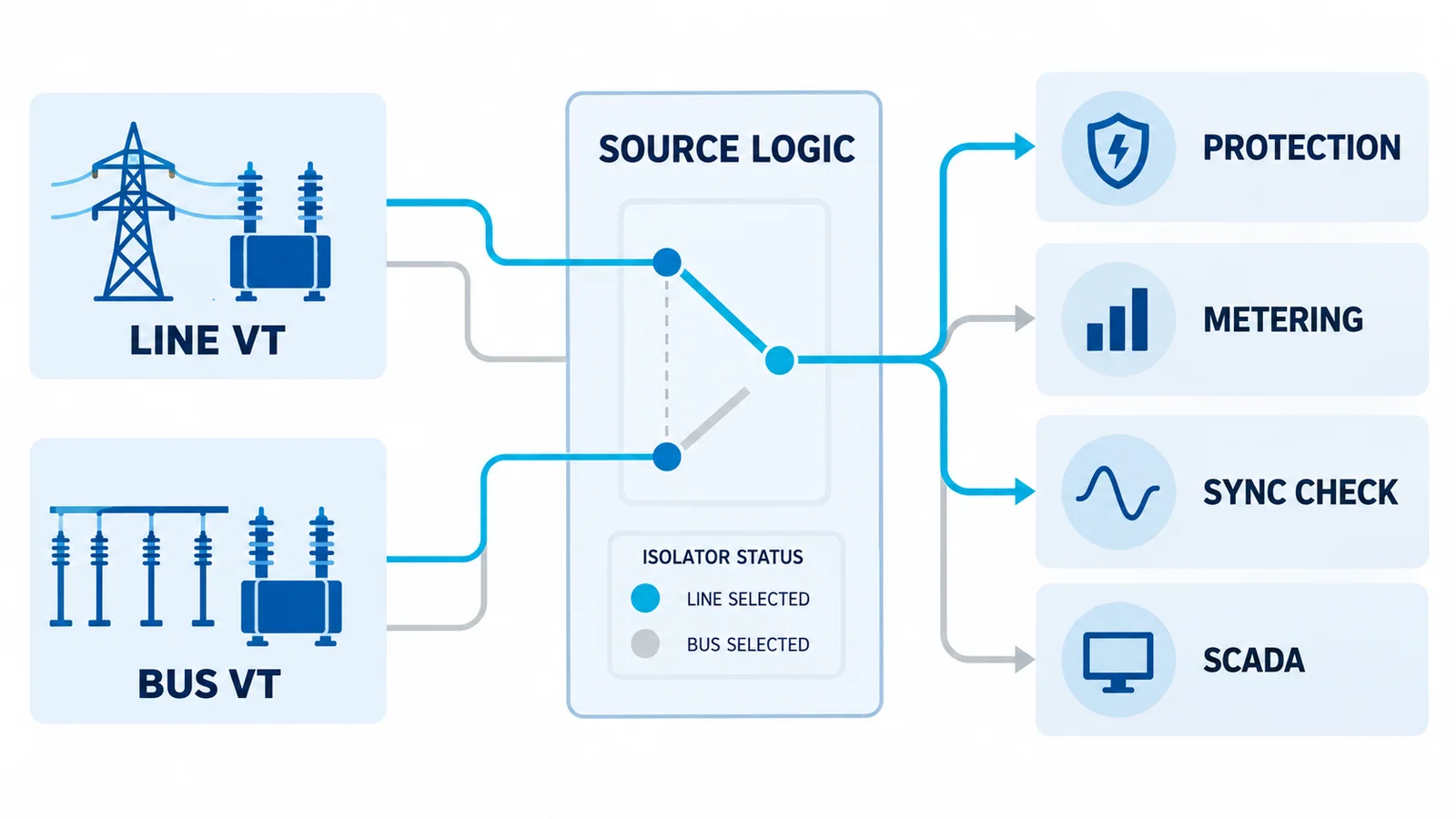
The matrix should include bus transfer, coupler open/closed, line outage, VT isolation, maintenance bypass, breaker failure and dead-bus conditions. Interlocking must prevent paralleling VT secondaries or selecting unrelated buses unless the design explicitly permits it.
Step 3: choose the VT technology
Inductive voltage transformer
IEC 61869-3:2011 applies to new inductive VTs used with measuring instruments and protective devices within its frequency scope.
An IVT is often favored where:
- accurate low-frequency voltage reproduction is needed;
- compact indoor or medium-voltage installation is practical;
- carrier coupling is not required;
- transient response for protection supports the application;
- ferroresonance risk is addressed by system and product design.
Capacitor voltage transformer
IEC 61869-5:2011 gives additional requirements for CVTs. A CVT is commonly considered at higher system voltages and may also support power-line carrier coupling. Its transient response, tuning, burden and ferroresonance behavior must be checked for the protection application.
Non-conventional or digital source
Low-power analogue or digital instrument-transformer systems can reduce copper wiring and support process-bus architectures. Selection then includes merging-unit compatibility, sampling, time synchronization, network redundancy, cybersecurity, latency and fallback behavior. Do not treat a digital output as a drop-in replacement for an analogue secondary.
Step 4: select location from topology
Single or sectionalized bus
A VT on each independently operable bus section usually provides clear bus-voltage ownership. If a bus coupler allows sections to combine, define whether sources remain separate or one source supplies selected functions.
Double-bus or main-and-transfer bus
Each bay may connect to more than one bus. VT selection logic must follow disconnect status and prevent an invalid source during transfer. Use positive position indications, discrepancy alarms and a fail-safe response; a single auxiliary contact should not be assumed sufficient without the station design basis.
Breaker-and-a-half
Line-side VTs/CVTs often provide a stable source for line protection, while bus VTs serve bus-voltage functions. The middle breaker means bay ownership and synchronism-check inputs must be defined per switching state. A “bus VT for everything” approach can leave a line function without the expected source during maintenance.
Transformer bays
Select the source according to the function’s electrical reference. Transformer V/Hz protection needs a voltage representative of the protected winding flux relationship; synchronism check needs voltages on the actual two sides of the breaker being closed.
For topology fundamentals, see distribution substation configurations and equipment.
Step 5: define primary rating and insulation requirements
Specify:
- nominal system voltage and highest voltage for equipment;
- connection phase-to-earth or phase-to-phase;
- system grounding and earth-fault factor where applicable;
- rated voltage factor and duration according to the selected standard/application;
- power-frequency and impulse withstand requirements;
- pollution, altitude, creepage and environmental conditions;
- indoor/outdoor construction and seismic/mechanical requirements.
IEC 60071-1:2019 provides the insulation-coordination principles used to select rated withstand voltages. It does not set human-safety clearances or prove that a specific VT is suitable for a site.
Step 6: choose ratio and secondary arrangement
Define the primary and each secondary voltage explicitly, including whether values are phase-to-phase or phase-to-neutral. Identify:
- number of metering and protection windings;
- three-phase set or single-phase arrangement;
- residual/open-delta winding where required;
- winding terminal designations and polarity;
- secondary grounding point;
- fuses or miniature circuit breakers according to the approved scheme;
- isolation/test links and safe maintenance state;
- cable shielding and routing.
Never short-circuit a VT secondary. This is the opposite of a CT secondary safety rule. The current-transformer installation guide explains that distinction for CT circuits.
Step 7: calculate burden by function and winding
For an analogue secondary, sum the connected device burden and lead burden on the same winding. For a simple two-wire circuit:
Rlead = 2ρL / A
and approximately:
VAlead = Vdrop × I = I²Rlead
The complete burden includes relay/meter inputs, wiring, switches, fuses and transducers. Keep metering and protection burdens assigned to their specified windings. Check both total burden and the accuracy performance at the actual burden/power factor required by the applicable standard and product data.
Do not oversize burden deliberately without the manufacturer’s application guidance. Modern numerical relays may impose low burdens, and some VT/CVT designs have minimum or damping considerations that must be handled as an engineered system.
Step 8: choose accuracy from the task
Metering and protection classes answer different questions. Specify:
- class and rated burden for each winding;
- revenue-metering requirements from the responsible authority;
- protection performance, including transient behavior where relevant;
- frequency/bandwidth needs for power-quality or synchrophasor functions;
- whether multiple connected devices preserve the required class;
- test and calibration evidence.
IEC and IEEE class designations are not interchangeable. In North American projects, IEEE C57.13-2016 provides requirements for instrument transformers within its scope; confirm the active project edition and utility rules.
Step 9: engineer transfer and failure logic
Voltage-source selection can fail silently unless validity is supervised. Consider:
- VT secondary fuse/MCB failure detection;
- phase-loss and low-voltage supervision;
- bus-disconnect position and discrepancy;
- source disagreement between redundant channels;
- manual test/maintenance selection;
- prevention of secondary backfeed or paralleling;
- fail-safe behavior of protection and synchronism functions;
- SCADA quality flags and alarms;
- event recording of source changes.
A low measured voltage can mean a dead bus, a primary VT problem, a secondary fuse failure, a wiring defect or a source-selection error. Logic must discriminate these states enough to avoid unsafe closing or unwanted protection blocking.
Specification checklist
Before procurement, confirm:
- applicable IEC/IEEE/national standard and edition;
- technology and installation location;
- primary ratio, connection and highest voltage for equipment;
- insulation and environmental requirements;
- each secondary winding’s voltage, class and burden;
- residual-voltage requirement;
- transient response and carrier-coupling needs;
- grounding, protection, isolation and test arrangement;
- terminal-box and cable-interface requirements;
- source-transfer logic and I/O;
- ferroresonance/damping provisions where applicable;
- routine/type/special test documentation;
- site commissioning and end-to-end functional tests.
Commissioning acceptance
Commissioning should verify more than ratio:
- nameplate, polarity and phase sequence;
- insulation and grounding according to the approved procedure;
- ratio and secondary voltages;
- burden and wiring continuity;
- fuse/MCB failure alarms;
- voltage-source selection in every permitted topology;
- synchronism-check inputs on both sides of each controlled breaker;
- protection, metering and SCADA scaling;
- absence of unintended secondary paralleling/backfeed;
- event and quality indications during source loss/transfer.
Work must be done by qualified personnel under approved isolation, lockout/tagout, absence-of-voltage verification and grounding procedures. Do not open primary circuits or alter energized VT secondaries based on this article.