
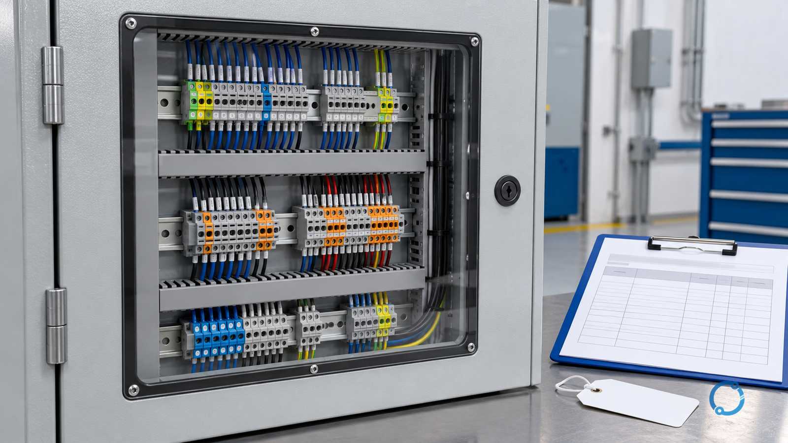
A discolored or unusually warm terminal block is a symptom, not a diagnosis. The heat may originate at the conductor-to-terminal interface, somewhere else in the same current path, or from conditions affecting the entire enclosure. Replacing the visibly hottest part before those possibilities are separated can leave the real defect in service.
The investigation also has a hard safety boundary. Smoke, arcing, visible melting, a loose connection while energized, damaged insulation or an unknown heat source requires the circuit to be placed in a safe state. Do not touch, tighten or probe an exposed live terminal. A qualified person should isolate the equipment, verify absence of voltage with the approved procedure and test instrument, control stored energy and establish the permitted work boundary before inspection.
This workflow applies to industrial and similar low-voltage control-panel terminal blocks. It focuses on the diagnostic path from observation to controlled return to service. It does not supply universal temperature limits, torque values or inspection intervals. Those values must come from the applicable product instructions, assembly design, installation rules and site procedures. In the U.S. general-industry context, 29 CFR 1910.333 establishes de-energization and qualified-person requirements; other jurisdictions use their own rules.
Start with an event record, not a replacement decision
The first useful output is a small evidence record. It should identify:
- the panel, circuit and terminal designation;
- when the heat was noticed and by what method;
- the load condition at the time;
- whether the symptom occurred at startup, after a load change or after a period of normal operation;
- whether there was smoke, odor, noise, intermittent control or a protective-device operation;
- the nearest upstream and downstream components;
- any recent termination, modification, motor replacement, drive change or load addition;
- the condition of adjacent terminals and the rest of the enclosure;
- whether the reported image was taken with the enclosure closed, open or during a transient external heat source.
This record prevents a common error: treating an isolated thermal image as a complete maintenance history. A terminal that appears hot after the panel has been in direct sun, with similar heating around it, belongs to a different investigation from one terminal that is hot while its neighbors remain cool under repeatable load.
Preserve the original condition before cleaning, loosening or moving conductors. Take overview photographs, record the terminal identities and note the position of any barriers, covers and ventilation components. If the installation permits safe measurement, record temperature and current at the same operating state. If safe measurement is not possible, the next step is de-energization, not an improvised live inspection.
Separate a local hot spot from whole-panel heating
Temperature difference is often more informative than a single value. Compare the terminal under investigation with:
- adjacent terminals of the same function;
- the other poles of the same circuit;
- the corresponding terminal on a similar circuit;
- the incoming and outgoing conductor at the same load;
- the panel ambient and the outside-air temperature;
- other equipment in the same enclosure.
A single isolated terminal that is consistently warmer than its neighbors points toward a local difference in contact interface, conductor preparation, current sharing or component condition. Several terminals of the same type warming together may indicate grouping, load, voltage drop, enclosure heat or a system-wide operating change. A warm enclosure with similar temperatures at many connections should not be “fixed” by tightening one terminal at random.
| Observation | A useful first question | What it does not prove |
|---|---|---|
| One terminal much warmer than its peers | Is the measurement valid and is current equal between paths? | That the terminal is undersized |
| Several connected terminals warm together | Is the whole circuit carrying more current or receiving more heat? | That every joint is loose |
| One phase warmer on a polyphase circuit | Is current balanced and are all conductors equivalent? | That the phase terminal is defective |
| The entire enclosure is warm | Are ambient, forced cooling, grouping or internal heat sources involved? | That enclosure-level temperature is acceptable |
| Heat follows a particular load or operating mode | Which load, harmonic content or duty cycle changes? | That the cause is an overload |
The comparison must be made under a known load. A cool image recorded after the circuit has been off has little diagnostic value. Conversely, two records at different load and ambient conditions cannot be subtracted as though the installation were a laboratory test.
Validate the temperature evidence
An infrared camera, contact thermometer and human touch answer different questions. Human touch is not an approved diagnostic method around energized electrical equipment. A thermal camera can locate a difference without directly touching a live part, but its result depends on instrument setup and the surface being viewed.
For an infrared survey, record the camera model or calibration status where the site procedure requires it, emissivity setting, reflected-temperature assumption, measured-distance and spot-size considerations, focus, range, palette-independent scale and the load at the time. Thermal reflections from busbars, metallic conduit, sunlight or nearby warm equipment can create misleading patterns. A shiny or low-emissivity terminal surface can read differently from a matte black cable insulation surface. The hottest pixel is not automatically the hottest conductor interface inside the assembly.
Electrical measurements require their own validity checks:
- use an instrument and probe rated for the installation;
- confirm the instrument is functioning within its approved test interval;
- select the correct alternating or direct current range;
- use true-RMS measurement where the circuit requires it;
- measure the conductor or terminal arrangement without changing the connection;
- record phase and neutral or line and return currents together where relevant;
- identify harmonic, pulsating or intermittent loads that make one displayed value incomplete;
- note whether the value was recorded at the same time as the thermal observation.
Do not infer conductor current from a temperature reading. The current path can be dissipating more heat because of contact resistance while carrying a normal load, or the temperature can be elevated because the panel is receiving heat from somewhere else. Current and temperature are separate evidence items.
Use an eight-gate diagnostic sequence
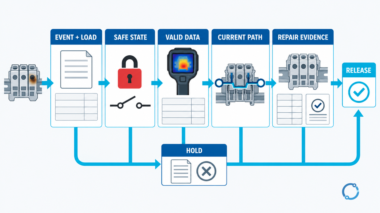
A useful sequence is to move from the event condition to the repair record. The gates are deliberately ordered: each later conclusion depends on the earlier evidence.
Gate 1: establish the reported symptom and operating state
Confirm what was observed and under which load. Record the exact terminal, conductor, phase and panel location. Include nearby signs such as discoloration, insulation hardening, odor, corrosion, loose strands, damaged barriers or deposits. Do not clean these signs away before documenting them.
Gate 2: place the circuit in a safe state
Isolate every source, including control supplies, back-feed paths, stored-energy devices and external signals that could energize the circuit. Follow the site lockout/tagout and verification procedure. Test for absence of voltage at the correct points and prove the tester before and after use where required. Allow capacitors or electronic assemblies to discharge according to their instructions rather than assuming that opening a disconnect removes all energy.
Gate 3: validate temperature and current evidence
Check whether the thermal image, measured temperature and current records are usable. Establish instrument limits, field of view, emissivity and load condition. Identify any readings taken at different times or under different loads. If an observation cannot be repeated safely, say so; an unexplained image is better treated as a prompt for inspection than as proof of a specific failure.
Gate 4: compare local heat with panel-wide heat
Classify the pattern as isolated, circuit-wide or enclosure-wide. Look for heat sources such as transformers, power supplies, drives, braking resistors, contactors or blocked ventilation. Compare similar circuits and phases. Consider whether the panel is operating with covers removed only for the measurement, because temporary opening changes cooling and can alter the result.
Gate 5: trace the complete current path
The hottest visible terminal may not be the highest-resistance point. Trace from the supply protective device through the busbar or distribution block, terminal, jumper, device contact, outgoing terminal and cable to the load. Check all screws, spring clamps, ferrules, cable lugs, splices and intermediate connections that carry the same current. A thermal difference can arise at the return path just as easily as on the line side.
For shared busbars and distribution blocks, verify that current is sharing as intended. An unequal conductor length, a poorly made tap, missing hardware or a loose stack can shift current into one connection. Do not assume that two conductors of the same nominal size carry equal current; measure each path where the design requires it and where safe access permits.
Gate 6: inspect conductor preparation and the clamping interface
With the circuit isolated, remove the conductor only as far as the approved repair procedure requires. Inspect the conductor end for:
- correct strip length and no insulation trapped in the clamp;
- cut, crushed, folded or missing strands;
- incorrect or damaged ferrule;
- solder flow, corrosion or contamination in a way that affects the termination;
- conductor size and class outside the terminal’s permitted range;
- mixed conductor materials or an unsuitable adapter;
- cable lug, washer or hardware incorrect for the assembly;
- signs of thermal damage extending beyond the terminal.
Inspect the terminal body, spring, screw, cage, contact surface, mounting foot and adjacent housing. A damaged clamp cannot be made acceptable by tightening it harder. Replace the terminal or conductor when the product instructions indicate that the part is no longer serviceable, and use the correct approved replacement rather than an apparently similar shape.
Gate 7: check load, grouping and enclosure conditions
A connection that is correctly made can still become hot if its complete thermal duty is different from the assumed duty. Review the recorded load against the circuit design and the applicable product data. Check ambient temperature, adjacent heat-producing devices, installation position, number of grouped circuits and ventilation. The installed conductor may be subject to derating that was never carried through to the terminal selection.
This is where the separate rating questions matter. Terminal-block current rating versus actual load explains how to compare the installed duty with the product rating. Reading terminal-block derating curves covers the manufacturer-specific temperature and grouping information. Neither calculation replaces inspection of a damaged contact surface, and a visual inspection does not replace the rating check.
Gate 8: define the repair and controlled release
After the failed assembly has been identified, decide whether the work is:
- cleaning and restoring a correct connection without damaging the terminal;
- replacing a conductor termination with the correct ferrule or lug;
- replacing the terminal, contact or associated hardware;
- correcting current sharing or a device connection;
- changing the enclosure thermal arrangement through an approved design change;
- replacing a larger assembly because local damage has affected insulation, barriers or adjacent components.
The repair instruction must identify the exact materials and approved procedure. Use the manufacturer’s torque value for the actual component and hardware combination. No generic torque value belongs in this article because terminal size, hardware, spring design and assembly requirements differ.
Distinguish the terminal from the assembly
IEC 60947-7-1:2025 defines an international product-standard scope for industrial or similar terminal blocks for copper conductors, including screw-type and screwless clamping units. Its existence helps identify the kind of product and the questions that a manufacturer should address. It does not prove that an installed terminal, conductor combination and assembly are suitable for the actual load.
The assembly context is separate. IEC 61439-1:2020 provides general rules and verification requirements for low-voltage switchgear and controlgear assemblies. That means a terminal can be electrically correct in isolation yet operate in an enclosure whose grouping, ambient, heat sources and cooling arrangement require a different assessment. For panel-level temperature patterns, see low-voltage switchgear operating temperature.
This distinction also affects repair evidence. A replacement terminal with the same physical pitch may have different terminal body material, spring force, conductor range, accessories or approval for the assembly. Use the controlled bill of materials and terminal-block selection for electrical panels when the original part is unavailable. Dimensions alone are not a cross-reference.
Trace beyond the hot terminal
The complete path is often longer than the visible link. A typical control circuit may run from a control transformer or supply, through a protective device, distribution terminal, door-mounted device, interposing relay, field terminal and field cable. Heat can travel by conduction from a remote contact, or a high-resistance joint can elevate a connected conductor that passes through several insulating parts.
Map the path on the actual drawing and then confirm it physically. Mark every separable interface:
- busbar or supply connection;
- terminal-block entry and clamp;
- jumper or bridge between blocks;
- device screw, spade or plug connection;
- door hinge or harness transition;
- field conductor termination;
- load return connection.
If the heat disappears at a nearby boundary, the problem may be upstream or downstream rather than at the apparent hot spot. The busbar joint overheating diagnostic method is relevant when the path includes a busbar joint, but a busbar defect should not be inferred from a hot terminal alone.
Use voltage-drop or resistance measurements only where the approved procedure and equipment make them meaningful. A simple resistance reading can be affected by contact probe placement, conductor temperature, parallel paths and the very small expected value. The result must be compared with controlled criteria, not treated as a universal pass/fail number. In many cases, physical evidence, repeatable thermal differences and a proper re-termination with verification are more informative than an uncontrolled micro-ohm measurement.
Decide between cleaning, re-termination and replacement
Cleaning may be appropriate when contamination is the primary issue and the contact surfaces, insulation and hardware remain within the product’s serviceable condition. Cleaning is not appropriate when the terminal has lost spring force, the clamp is deformed, the housing is heat-damaged or the conductor has lost strands. In those cases, “clean and retighten” hides a permanent defect.
Re-termination requires the correct preparation. Use the specified strip length, conductor class, ferrule or lug, insertion depth and tooling. Keep the conductor fully seated and verify the clamp position according to the product instructions. Replace any conductor with shortened, overheated or damaged insulation where the applicable installation requirements call for replacement.
Replacement should preserve function as well as current rating. Check terminal type, conductor range, voltage and insulation requirements, mounting rail, accessories, marking system and any assembly-specific approval. Current and thermal ratings are affected by the complete mounting and grouping arrangement; a catalog image with the same footprint is not enough.
If the evidence suggests that the original terminal is correct and the load or enclosure condition changed, replacing it with an identical part may simply reproduce the symptom. Record the system change and obtain an approved design decision before changing the circuit’s current or thermal duty.
Build a return-to-service record
The repair is not complete when the terminal feels tight. A controlled release should answer:
- What evidence identified the original condition?
- Which components, conductors and interfaces were inspected?
- What was replaced, re-terminated or left unchanged?
- Were the correct product and installation instructions used?
- Was the conductor condition correct before insertion?
- Was the documented tightening or clamping method used?
- Were barriers, covers, ventilation and markings restored?
- Was the circuit tested and returned under a defined load?
- Was the thermal condition compared with the pre-repair result?
- Who accepts the result, and what monitoring follows?
For the first loaded check, use a defined operating state rather than a casual visual glance. Record current, ambient, temperature pattern and any abnormal sound or odor. Compare the repaired terminal with its peers. If the temperature remains abnormal or the evidence shows a wider assembly problem, stop and return to the investigation rather than tightening the connection again.
The exact requalification interval should come from the site’s reliability and safety procedure. A short immediate check, a longer trend check, or thermal monitoring under the worst credible load may each be appropriate. The deciding factor is the evidence and consequence of failure, not a copied interval from another panel.
What the evidence cannot prove
A thermal image cannot, by itself, prove that a terminal is loose. A current reading cannot prove that the conductor preparation is correct. A resistance measurement cannot prove that a spring clamp retains its force after thermal cycling. A manufacturer’s product standard cannot prove that a particular assembly is compliant. A terminal replacement cannot prove that the enclosure thermal design remains adequate.
Keep those limits visible in the repair narrative. The investigation should explain which claim is supported by which observation and which decisions still require the product instructions, assembly design, local code or a competent engineering review.
Prevention starts with the next change
Most recurring terminal overheating is not fixed by adding an inspection to a spreadsheet. It is prevented when changes are controlled:
- conductor substitutions preserve size, class, material and termination method;
- new loads are checked against the complete circuit and terminal thermal duty;
- terminal replacements are chosen by function and approved specification, not only footprint;
- panel additions preserve grouping, cooling and barrier arrangements;
- maintenance records retain the terminal identity, load and correction;
- thermal surveys use consistent load, instrument settings and comparison references.
When a terminal overheats, the useful lesson is not simply “retighten terminals.” It is that a connection is part of a thermal and electrical system. Diagnosis becomes reliable when the event, safe state, measurement validity, current path, assembly conditions and repair evidence are treated as one record.
Sources
- IEC 60947-7-1:2025: Low-voltage switchgear and controlgear – Part 7-1: Ancillary equipment – Terminal blocks for copper conductors, published 2025, edition 4.
- IEC 61439-1:2020: Low-voltage switchgear and controlgear assemblies – Part 1: General rules, published 2020, edition 3.
- 29 CFR 1910.303: General electrical requirements, accessed 2026-10-28. This is a U.S. general-industry occupational-safety rule, not a universal IEC product standard.
- 29 CFR 1910.333: Selection and use of work practices, accessed 2026-10-28. This is a U.S. general-industry occupational-safety rule, not a universal IEC product standard.