

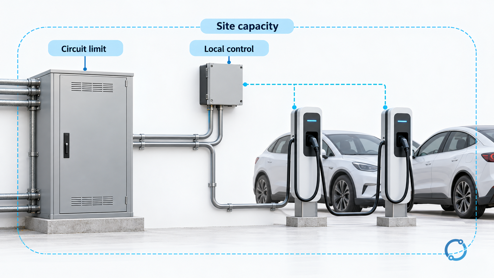
A smart AC EV charging installation is ready only when its physical circuit limits and load-management behavior have been verified. A “32 A” or “80 A” charging-output label is not an upstream breaker selection, and a current slider in an app is not proof that a site capacity limit will remain enforced.
This is a qualified-person commissioning framework for U.S. building-side AC electric vehicle supply equipment (EVSE). It does not provide a universal terminal diagram, conductor size or breaker rating. It excludes DC fast charging and bidirectional power-transfer wiring. The endpoint is an approved limit register with recorded normal, failure and restoration tests—not merely a successful charging session.
Establish three different limits before installation
| Limit | What it describes | Evidence to retain |
|---|---|---|
| EVSE output limit | Maximum current the equipment is permitted to make available to the vehicle | Listed equipment instructions, approved configuration and access controls |
| Branch-circuit limit | What the installed conductors, connections and protection are designed to supply | Approved circuit design, installation conditions and inspection record |
| Site or managed-group limit | Available capacity allocated to a group of charging loads | Approved capacity assessment, control architecture and verified measurement boundary |
The vehicle may accept less than the available current. That behavior is not evidence that the circuit would remain within its design limit when a different vehicle, configuration or operating condition demands more.
The DOE Alternative Fuels Data Center infrastructure guide identifies utility capacity, permitting, applicable electrical codes and equipment considerations as part of installation development. Confirm the adopted code edition and authority having jurisdiction (AHJ), along with the equipment’s listing and installation instructions. Do not infer a universal 40 A or 100 A upstream rating from the two example output labels.
The existing circuit-breaker sizing guide explains generic coordination questions. Apply the additional EVSE-specific requirements through the approved project design rather than treating generic sizing as a complete EV installation rule.
Define where the management system measures and enforces capacity
Trace the control boundary before commissioning: which circuits are measured, which charging points are controllable, where the limit is enforced and which other building loads share capacity. A controller using an incomplete measurement boundary can report compliance while missing a material load.
Distinguish scheduling from a capacity-limiting function. A schedule that postpones charging may help operations, but its existence does not prove that the electrical design’s required limit is enforced. If reduced infrastructure capacity relies on load management, the adopted rules and approved system arrangement must permit that reliance.
DOE FEMP guidance on smart charge management addresses system integration, communications and commissioning. The practical acceptance question is whether the installed combination—not just one software feature—behaves as specified.
Record the behavior expected if communications, measurements, controller power or cloud access are lost. Do not assume every system stops charging, or that continued charging is always unacceptable. Its response must match the approved design, equipment capabilities and available capacity.
Complete physical checks before functional tests
Qualified personnel should compare the installed circuits with approved drawings and instructions, including conductor routing, connections, protective arrangements, equipment ratings and identification. Inspect and test using the applicable safe procedures; this guide does not authorize live adjustments or bypassing protective functions.
Confirm that the commissioned EVSE configuration agrees with the circuit record. Restrict changes that could invalidate it. Also identify the protective functions required for the installation: conventional overcurrent protection, personnel protection and any EVSE-specific functions must not be conflated. The GFCI versus AFCI guide explains those different hazard objectives, but does not select the protective device for this EVSE model.
Resolve missing instructions, unverified listing conditions, unexplained circuit changes or uncertain earthing/protective paths before proceeding. A powered display and a charging indicator are not substitutes for these checks.
Test the installed operating envelope
The following scenarios are an editorial acceptance framework to adapt to the approved design—not a universal DOE-mandated test sequence. Use controlled test conditions, appropriate instrumentation and an authorized commissioning plan.
| Scenario | Observe and record | Acceptance question |
|---|---|---|
| One point requesting maximum available charging | Output behavior, circuit loading and configured limit | Does the commissioned configuration stay within its permitted duty? |
| Several points requesting charge together | Group allocation and relevant site measurements | Is the actual shared capacity boundary respected? |
| Other building loads changing | Measurement response and charging allocation | Does the approved control account for those loads? |
| Loss of a relevant communication or measurement input | Reported state and actual charging response | Does it enter the documented permitted failure state? |
| Restoration after interruption | Startup, limit retention and group behavior | Are limits preserved before normal charging resumes? |
| Authorized configuration change | Permissions, audit record and affected limits | Is revalidation triggered where the design basis changes? |
An unloaded or vehicle-limited trial may not exercise the maximum-demand scenario. State that limitation explicitly and arrange a suitable approved test method; do not record an unexercised capacity function as passed. Similarly, a simulated communications alarm without observing output does not prove the physical response.
Handover includes the conditions for staying commissioned
Retain the circuit and limit register, inspection results, configuration version, measurement mapping, test scenarios and observed failure/restoration behavior. Assign responsibility for reviewing changes in software, hardware, site loads and charging-point count.
DOE FEMP’s applications guidance describes coordinated charging within available capacity. That operational benefit depends on a maintained system boundary. Adding another charger or changing controller settings can invalidate the original acceptance record even if every point still charges successfully.
For the broader difference between remote features and electrical specification, see the intelligent breaker and switchgear specification guide. Release this EV installation only when physical protection and managed behavior both match the approved design and the required inspection/approval is complete.