
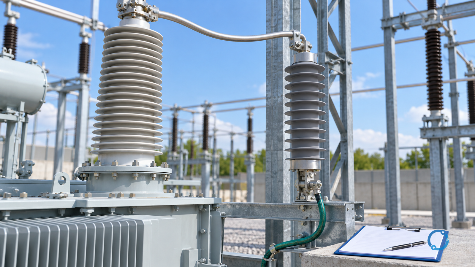
Selecting a surge arrester for a transformer begins with the terminal being protected, not with a product family. The reviewer must know the system voltage and earthing, the temporary overvoltage duty the arrester can experience, the protective level required at the equipment, the surge-current and energy environment, and the physical path from the line terminal through the arrester and its earth connection.
Those inputs do not fit into one catalogue column. A voltage rating alone does not establish protection, and a low discharge voltage alone does not establish survivability. The selection must be coordinated with the transformer insulation, the station arrangement and the governing study.
IEC 60099-5:2018 provides selection and application recommendations for surge arresters in three-phase systems with nominal voltages above 1 kV. IEC 60071-1:2019 establishes the insulation-coordination procedure for selecting rated withstand voltages for equipment above 1 kV, and IEC 60071-2:2023 provides application guidance. Together they frame this article’s boundary: the task is to assemble and verify a specification, not to replace the insulation-coordination study with a generic selection table.
Begin at the protected terminal
A transformer can have several terminals with different insulation levels, surge environments and consequences of failure. “Protect the transformer” is therefore too broad to select an arrester. Start with the exact point:
- Which winding terminal, bushing, cable termination or switchgear interface is exposed?
- Is the arrester intended to protect the transformer alone, a connected switchgear section, an incoming line or the whole station node?
- Is the terminal overhead-fed, cable-fed, gas-insulated, directly connected to a line or separated by a significant length?
- What other arresters or surge-protective devices already influence the node?
- Is the transformer solidly earthed, impedance-earthed, isolated from earth, or operated under another earthing condition?
The answer defines the voltage seen by the arrester, the distance over which the protective path acts and the equipment whose insulation levels must enter the coordination study. A well-selected arrester installed electrically far from the protected terminal can leave a voltage difference across the connecting leads that subtracts from its catalogue protection.
Record the terminal reference in the same place as the system data and the study boundary. A specification without that reference is difficult to review because two engineers can each assume a different winding.
Establish the voltage and earthing duty
The arrester is continuously connected to a system condition. The task is not merely to match the highest voltage for equipment; it is to identify the maximum power-frequency voltage the arrester may see over the required duration, including temporary overvoltages.
The input record should distinguish:
- highest voltage for equipment at the location;
- nominal system voltage and operating voltage range;
- system earthing and transformer neutral arrangement;
- conductor arrangement and any coupling or resonance conditions that can sustain voltage;
- possible single-phase earth faults and their clearing times;
- load rejection, generator overvoltage or other temporary-overvoltage sources relevant to the scheme;
- planned switching states, including an isolated transformer or a de-energized section that remains coupled to other circuits;
- voltage at the arrester location, not only at a remote source bus.
IEC 60099-5 is an application guide, not a table that supplies every project’s temporary-overvoltage duty. The governing study or the responsible utility practice must establish the voltage-versus-time input. If an assumption about earthing or fault clearing cannot be verified, the specification is incomplete.
Do not describe the highest system voltage as if it were the only voltage stress. A temporarily sustained voltage can matter even when the normal operating voltage appears unremarkable. The value, waveform and duration must be stated with the protection basis.
Separate rating, protection and capability
A surge-arrester selection review becomes clearer when three questions are written separately:
- Voltage duty: can the arrester withstand the continuous and temporary power-frequency voltage at the location?
- Protective level: what voltage remains at the equipment end of the installed path during the relevant impulse condition?
- Capability: can the arrester absorb the specified current and energy without loss of its required protective function?
These questions cannot be averaged into one margin. A lower protective level could be attractive, but it may conflict with the voltage-duty requirement. A high energy capability does not guarantee a low protective level. A voltage rating that seems adequate for normal operation does not establish coordination with transformer insulation.
State the unit and reference of every claimed value. Residual voltage, maximum continuous operating voltage, temporary-overvoltage capability and energy rating are different quantities and should not be substituted for each other.
Turn system data into a selection input matrix
Use a table to make the trace visible rather than collecting a set of disconnected catalogue pages.
| Input | Required evidence | Decision it constrains | Minimum record |
|---|---|---|---|
| Protected terminal | Single-line diagram, equipment tags, station layout | Which winding, node and insulation level are coordinated | Terminal and asset identifier |
| Highest voltage | Transformer and system documentation | Basic voltage and insulation-level context | Um, voltage class, source |
| Earthing and neutral | Earthing drawing and operating arrangement | Temporary-overvoltage and fault-duration questions | Earthing condition, fault-clearing logic |
| Power-frequency voltage duty | Operating and study record | Arrester voltage capability | Voltage versus time, basis |
| Lightning/switching environment | Station exposure and system study | Current duty and protective coordination | Study reference and scenario |
| Protective level at equipment | Arrester data plus lead and earthing geometry | Minimum insulation margin | Voltage at the equipment node |
| Current/energy capability | Applicable standard, test basis, project duty | Ability to survive required stress | Matching duty units and waveform |
| Installation geometry | Layout, separator and lead route | Actual protective path | Length, route, earth connection |
This matrix is an interface between the transformer, earthing, insulation-coordination, station-layout and arrester-data owners. It is not a substitute for any one of their studies.
Coordinate with the transformer insulation system
The arrester protective level is useful only in relation to the insulation strength at the protected terminal and to the separation between them. The relevant check should use the insulation-coordination methods and withstand-voltage definitions in the applicable study, not a universal percentage or an unverified “safety margin”.
IEC 60071-1 defines the procedure for selecting rated withstand voltages for equipment and installations in three-phase AC systems above 1 kV. Its association between standard withstand voltages and highest voltage for equipment is an insulation-coordination convention; it is not a statement that human safety requirements are covered by the document. IEC 60071-2 provides application guidelines, including detailed simulation as part of the current edition.
The specification should therefore record:
- the transformer terminal insulation level as stated in the verified equipment documentation;
- the protective level calculation at that terminal;
- the coordination factors, impulses and waveform assumptions used by the appropriate study;
- the lead-induced voltage difference and earthing geometry included in the comparison;
- the conclusion, reviewer and any residual uncertainty.
Never infer compliance or adequacy because an arrester and a transformer are both covered by general standards. A standard defines a domain and a method; it does not certify a specific combination.
Include the full protective path
The arrester is not an isolated component located at a point on a diagram. The path from the protected line terminal through its leads, the arrester, the earth conductor and the station earth carries the surge current. Its physical arrangement belongs in the selection.
Ask for:
- line-side lead length, route and bend geometry;
- earth-side lead length and shared-current route;
- arrester mounting orientation and phase spacing;
- proximity to transformer bushing, cable termination and other equipment;
- whether the earth connection is direct, separated or shared;
- touchable and isolatable parts, insulating barriers and maintenance access;
- environmental conditions that can affect insulation surfaces or connections;
- the earthing-system path over the relevant frequency range, as required by the study.
No generic lead-length limit is supplied here because the acceptable arrangement depends on the arrester, voltages, insulation margins and station configuration. The safe statement is more demanding, not less: the protective path must be explicitly modeled or evaluated and verified against the governing application study.
IEC 60099-5:2018 covers selection and application across several categories of metal-oxide and gapped arresters. Its scope does not erase the need for an approved station design, manufacturer instructions and local standards in force.
Current and energy duty need the same rigor as voltage
Surge current and energy duty depend on the system and the event. The reviewer should identify the relevant cases, including lightning attachment or incoming-surge conditions, switching events, temporary fault mechanisms and the consequences of an arrester operation.
Do not turn an impulse-current number into a generic “energy margin”. The required comparison needs:
- waveform and duration;
- amplitude and charge, where applicable;
- number of impulses and sequence;
- thermal recovery condition and initial temperature assumed by the application study;
- relevant protective function after the event;
- test basis and the current product standard.
IEEE C62.11-2020 is an active IEEE standard for metal-oxide surge arresters for AC power circuits above 1 kV. It defines product tests and ratings for surge arresters under its scope. It is not a project-specific selection instruction. The application guidance is being revised in IEEE PC62.22, which is an active standards project. IEEE C62.22-2009 is inactive-reserved and should not be presented as the current active application instruction.
For a specification, use the active standard and the approved project method, and ask the equipment supplier to provide the tested characteristic that matches the relevant duty. Do not fill a blank with a universal margin because a value is absent.
Write the specification as a verifiable chain
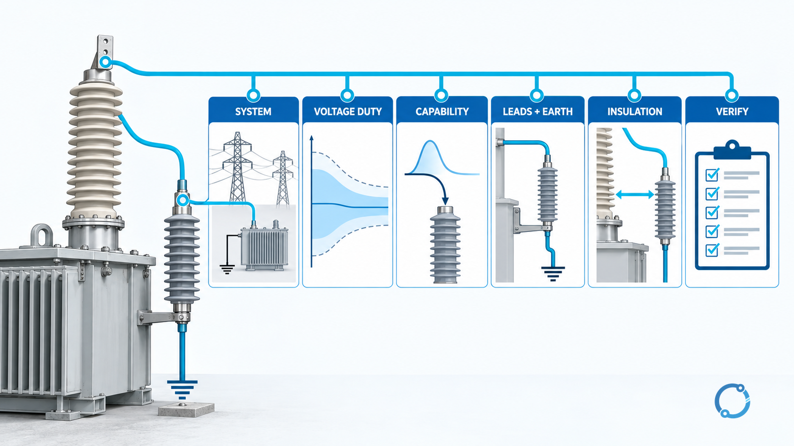
A defensible specification can be structured as follows:
- Protected node. State the transformer terminal and the connected equipment within the protection boundary.
- System basis. State voltage, frequency, earthing, fault-clearing conditions and relevant operating states.
- Voltage duty. Provide the maximum continuous and temporary voltage conditions with duration and source.
- Protective requirement. State the maximum voltage that the protected equipment can tolerate at the terminal, including the effect of the connecting path.
- Arrester characteristics. Specify voltage rating or MCOV, protective level, pressure-relief behavior, mechanical and environmental requirements as verified against the applicable support.
- Current and energy duty. State the study case and the required capability using consistent units and testing basis.
- Geometry. Include lead routes, separation, earthing and the station interfaces that affect protection.
- Testing and acceptance. State the evidence expected for the delivered device, plus installation inspection and record requirements.
- Change control. Record any change in system earthing, transformer insulation level, line connection or station layout and reopen the study.
This chain prevents a purchase order from losing the assumptions that justified the selected device.
Address installation and maintenance before approval
The installed device must remain inspectable and replaceable without introducing a new hazard. Include:
- isolating and earthing provisions required by the site;
- safe access and lifting arrangements;
- pressure-relief or failure-containment requirements applicable to the installation;
- environmental protection appropriate to pollution, humidity, salt, dust or altitude;
- condition indicators and their approved interpretation;
- a maintenance and replacement plan tied to the manufacturer’s instructions and site practice;
- identity marking and a record of the installed rating, serial number and test evidence.
Do not interpret an indicator alone as a complete condition assessment. Do not touch, disconnect or test an installed arrester unless authorized under the site’s electrical-safety procedure.
For broader surge-protection context at the low-voltage interface, the SPD selection guide for TN, TT and IT earthing belongs to a different voltage and device scope. It should not be used to select a high-voltage transformer arrester.
Answer the selection question with a bounded conclusion
A useful conclusion names the inputs, records the decision and states what remains unknown:
For transformer terminal T-01, the selected arrester must satisfy the system voltage and temporary-overvoltage duty stated in the project study, provide a coordinated protective level at the transformer terminal after the modeled lead and earth path are included, and demonstrate the specified current and energy capability. Final approval requires verification against the transformer insulation study and the approved station layout.
That is deliberately not a one-line product order. It gives a reviewer something to check: terminal, duty, protection, capability, geometry and evidence.
Selection checklist
Before the selection is issued for approval, verify:
- the protected transformer terminal is named;
- system earthing and temporary-overvoltage conditions are documented;
- the voltage duty includes duration, not only a nominal value;
- protective level is stated at the protected equipment, not only at the arrester terminals;
- current and energy capability are tied to defined waveforms and test bases;
- line and earth leads are included in the protective path;
- the transformer insulation level and applicable coordination method are referenced;
- standards editions and their status are correctly stated;
- the device can be installed, inspected and replaced as part of the approved station design;
- unresolved assumptions are visible and assigned to an owner;
- any change to earthing, layout, transformer insulation or system arrangement triggers a review.
If a critical input is missing, the correct output is an open action, not a confident product recommendation.
Sources
- IEC 60099-5:2018: Surge arresters, Part 5: Selection and application recommendations, published January 2018, edition 3.0.
- IEC 60071-1:2019: Insulation co-ordination, Part 1: Definitions, principles and rules, published 2019, edition 9.0.
- IEC 60071-2:2023: Insulation co-ordination, Part 2: Application guidelines, published 2023, edition 5.0.
- IEEE C62.11-2020: Standard for Metal-Oxide Surge Arresters for AC Power Circuits (>1 kV), active standard.
- IEEE PC62.22: Application Guide for Metal-Oxide Surge Arresters for Alternating-Current Systems Over 1000 Volts, active PAR. IEEE C62.22-2009 is listed as inactive-reserved.