
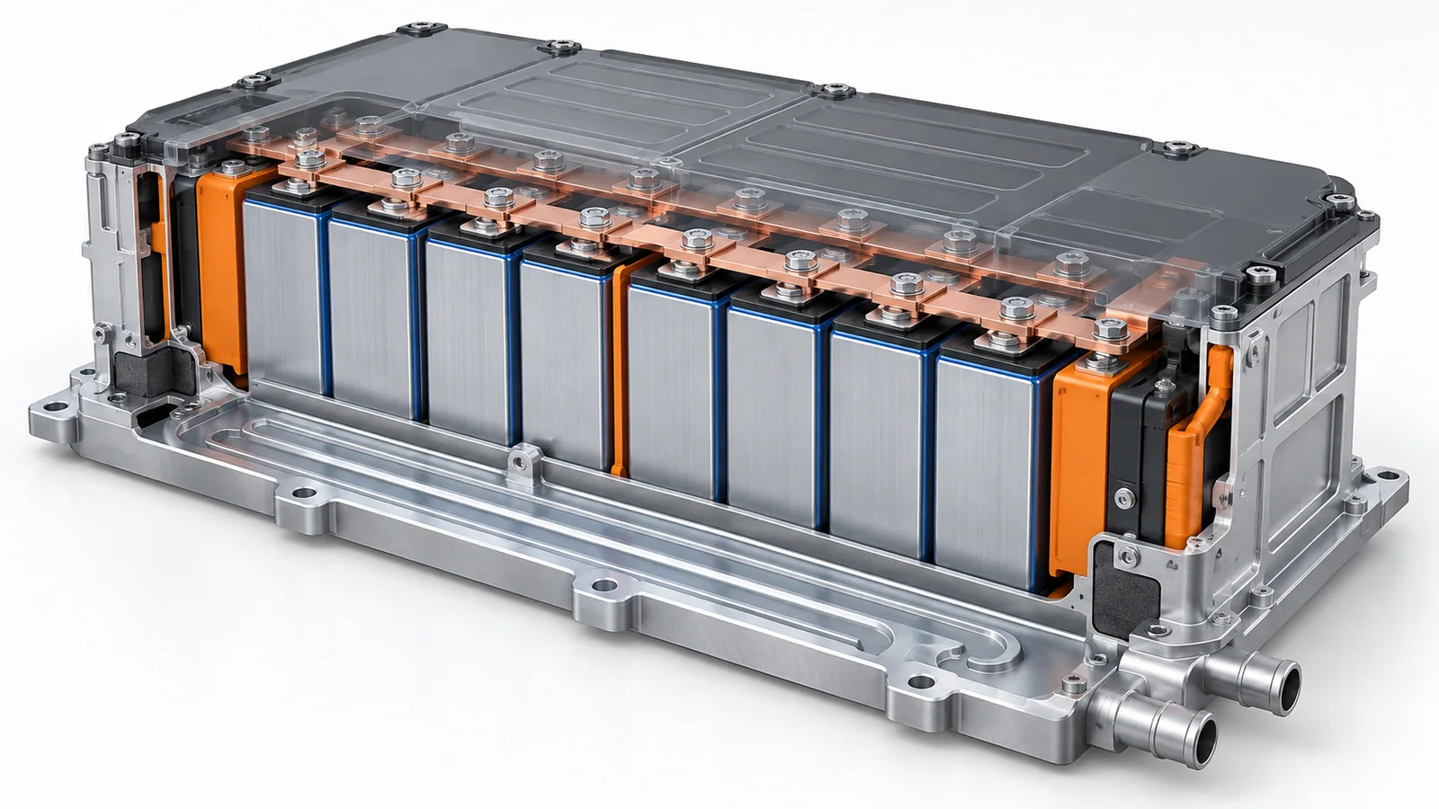
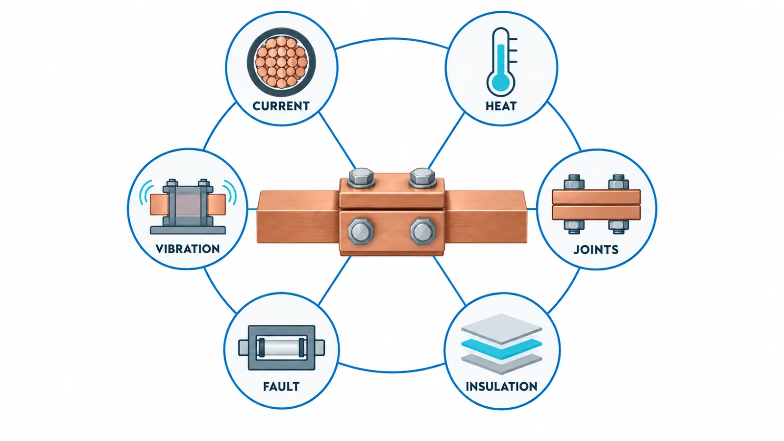
Size an EV battery busbar from the actual continuous and pulse-current duty using resistance at operating temperature, then validate joints, cooling, insulation coordination, fault forces, vibration, manufacturing tolerance and vehicle-level safety. A universal ampacity or current-density value is not enough because the pack enclosure, cell interfaces, duty cycle and cooling path determine temperature.
The deliverable is a validated current path, not just a copper cross-section.
Scope
This guide covers rigid and flexible conductive links inside a traction-battery pack or module. It addresses preliminary electrical, thermal, insulation and mechanical design. It does not specify cell chemistry, battery-management algorithms, crash structure or service procedures.
ISO 6469-3:2021 specifies electrical-safety requirements for voltage-class-B propulsion circuits and conductively connected auxiliary circuits, including protection against electric shock and thermal incidents. It explicitly does not provide complete safety information for manufacturing, maintenance or repair personnel.
UN Regulation No. 100 Revision 3 provides vehicle type-approval requirements for electric power trains and rechargeable electrical energy storage systems in its jurisdictional scope. Component calculations must ultimately support the applicable vehicle-level requirements.
Step 1: define the electrical duty cycle
Record current as a function of time:
- maximum continuous traction current;
- repeated acceleration pulses;
- regenerative-braking current;
- fast-charge current;
- low-temperature and high-temperature operating cases;
- fault current and protection clearing time;
- cell/module imbalance assumptions;
- expected life-cycle count.
Peak current alone cannot set area. A 10-second pulse repeated every minute produces a different temperature trajectory from one pulse followed by a long cool-down.
For an interval with approximately constant current:
E = I²Rt
where:
- E is Joule energy;
- I is current;
- R is resistance at the interval temperature;
- t is duration.
For a changing duty:
E = ∫ I(t)²R[T(t)] dt
The thermal model must account for changing resistance and heat removal. RMS current over a defined cycle can be useful:
Irms = √[(Σ Ii²ti) / (Σ ti)]
Use RMS only when the thermal time constants and repeating cycle make the averaging meaningful. It does not replace peak-force or short-circuit checks.
Step 2: choose material and preliminary area
For a uniform conductor:
R20 = ρ20L / A
Rθ = R20[1 + α20(θ − 20)]
Copper offers lower resistance for a given area; aluminium can reduce mass but needs a larger section and carefully engineered joints. Plating, laminated construction and flexible sections change interfaces and mechanical behavior.
Select a preliminary area from:
- permitted steady temperature;
- pulse temperature rise;
- voltage-drop budget;
- mass and package volume;
- joining process;
- stiffness/flexibility;
- corrosion compatibility;
- manufacturing tolerances.
Do not transplant an enclosure busbar ampacity table into a battery pack. Cooling surfaces, duty cycle and insulation differ.
Worked resistance and pulse example
Assume an illustrative copper link:
- length: 0.30 m;
- width: 30 mm;
- thickness: 3 mm;
- area: 90 mm²;
- illustrative resistivity at 20°C: 0.01724 Ω·mm²/m.
Cold resistance:
R20 = 0.01724 × 0.30 / 90 ≈ 57.5 µΩ
At an estimated 80°C conductor temperature using α20 = 0.00394/°C:
R80 ≈ 57.5 × [1 + 0.00394 × 60] ≈ 71.1 µΩ
At 400 A:
P = 400² × 71.1 µΩ ≈ 11.4 W
For a 15-second pulse with negligible heat removal during the pulse:
E ≈ 11.4 × 15 ≈ 171 J
That energy result is an input to a transient thermal model. It does not predict temperature without conductor heat capacity, joint losses and heat transfer to cells, cooling plates, insulation and pack air.
Step 3: build the thermal network
Represent heat paths from:
- conductor bulk;
- welded, bolted or bonded joints;
- cell terminals;
- contactors and fuses;
- flexible links;
- insulation and supports;
- cooling plates or pack structure;
- internal air/coolant;
- external vehicle environment.
Evaluate:
- hot soak after parking;
- cold start and fast charge;
- blocked or degraded cooling;
- adjacent-cell heat;
- repeated pulse accumulation;
- temperature sensor location and lag;
- tolerance stack for material and joints.
The hottest joint can govern before the straight bar. Include measured or validated interface resistance rather than distributing all loss uniformly.
Step 4: design the joints
Joint design controls resistance, durability and manufacturability. Define:
- material pair and plating;
- weld process or bolted interface;
- contact area and pressure;
- flatness and surface preparation;
- thermal expansion mismatch;
- flexible relief for cell swelling or vibration;
- corrosion and electrolyte exposure;
- inspection and end-of-line test.
For bolted joints, torque is a process input, not a direct measurement of contact pressure. Control fastener condition, friction, washers and assembly method. For welded joints, control energy, force, geometry and inspection criteria.
Use four-wire resistance measurement where appropriate to separate micro-ohm-level joint changes from lead resistance.
Step 5: coordinate insulation
Insulation design depends on:
- maximum working voltage and transients;
- pollution/contamination inside the pack;
- altitude;
- material group and tracking performance;
- clearances and creepage distances;
- solid insulation thickness;
- edges, burrs and coating processes;
- condensation and coolant/electrolyte exposure;
- manufacturing tolerances and movement.
IEC 60664-1:2020+A1:2025 provides insulation-coordination principles for equipment within its voltage scope. Vehicle standards and project specifications may impose different or additional requirements. Use the applicable framework; do not copy one clearance number without its overvoltage, pollution, altitude and material context.
Sleeving or coating does not eliminate clearance, defect, edge and aging concerns. Validate after forming, joining and assembly.
Step 6: check fault and contactor duties
The battery can deliver high DC fault current. Determine:
- maximum prospective fault current;
- current rise and source impedance;
- fuse/contactors’ clearing behavior;
- let-through energy;
- busbar thermal withstand;
- peak electromagnetic force;
- arc and plasma containment;
- fault location relative to cells and enclosure.
Use device-specific validated data internally for the exact fuse and contactor. Do not assume a fuse’s nominal current predicts its clearing energy.
Short-circuit force can move a busbar before thermal limits are reached. Verify supports, joint loads and clearances under peak current.
Step 7: design for movement and crash environment
Battery packs see:
- vibration spectra;
- mechanical shock;
- cell swelling;
- thermal expansion;
- body/chassis deflection;
- manufacturing variation;
- crash deformation.
Rigid bars can transfer load into cell terminals. Flexible laminated or braided links can accommodate movement but add resistance, joining and insulation variables. Select flexibility from measured displacement and load limits, not visual preference.
Vehicle-level crash integrity is outside a simple busbar calculation. The busbar layout should support the isolation, retention and post-event safety strategy established by the applicable vehicle requirements.
Step 8: control sensing and service boundaries
Voltage-sense leads, temperature sensors and current sensing can affect layout. Define:
- sense-point location;
- fusing or protection of small conductors;
- routing and isolation;
- connector retention;
- diagnostic coverage;
- safe service disconnect boundary;
- touch protection after covers are removed under the service procedure.
Do not use the article as a service instruction. High-voltage battery work requires vehicle-specific procedures, qualification, isolation verification and appropriate PPE.
Requirement-to-validation matrix
| Requirement | Analysis | Prototype/production evidence |
|---|---|---|
| Continuous current | hot resistance and steady thermal model | thermal test at defined ambient/cooling |
| Pulse duty | transient I²Rt model | representative duty-cycle test |
| Voltage drop | resistance network | four-wire path measurement |
| Joint stability | contact/weld process model | resistance, thermal cycling, section/inspection |
| Insulation | coordination study | dielectric/insulation tests and process inspection |
| Fault duty | circuit and let-through model | validated component/pack fault evidence |
| Vibration | mechanical model | environmental durability test |
| Tolerance | worst-case stack and sensitivity | capability data and end-of-line limits |
| Vehicle safety | system hazard analysis | applicable ISO/UN vehicle evidence |
Design-review checklist
- Define continuous, pulse, charge and regenerative currents.
- Calculate hot conductor and joint resistance.
- Allocate voltage drop and heat by segment.
- Model transient and steady temperatures.
- Validate cooling-degraded and ambient extremes.
- Design joints and production controls.
- Complete insulation coordination with tolerances.
- Verify fault thermal and electrodynamic duty.
- Validate vibration, shock and movement.
- Integrate sensing, contactors, fuses and service disconnect.
- Map component evidence to vehicle-level safety requirements.
- Freeze drawings, materials, process limits and tests.
Bottom line
EV battery busbar design starts with the current-versus-time profile and ends with vehicle-level validation. Calculate resistance at operating temperature, model pulse energy and cooling, treat joints as separate heat sources, coordinate insulation and verify fault forces and mechanical durability. Cross-section is only one variable in a safety-critical current path.