
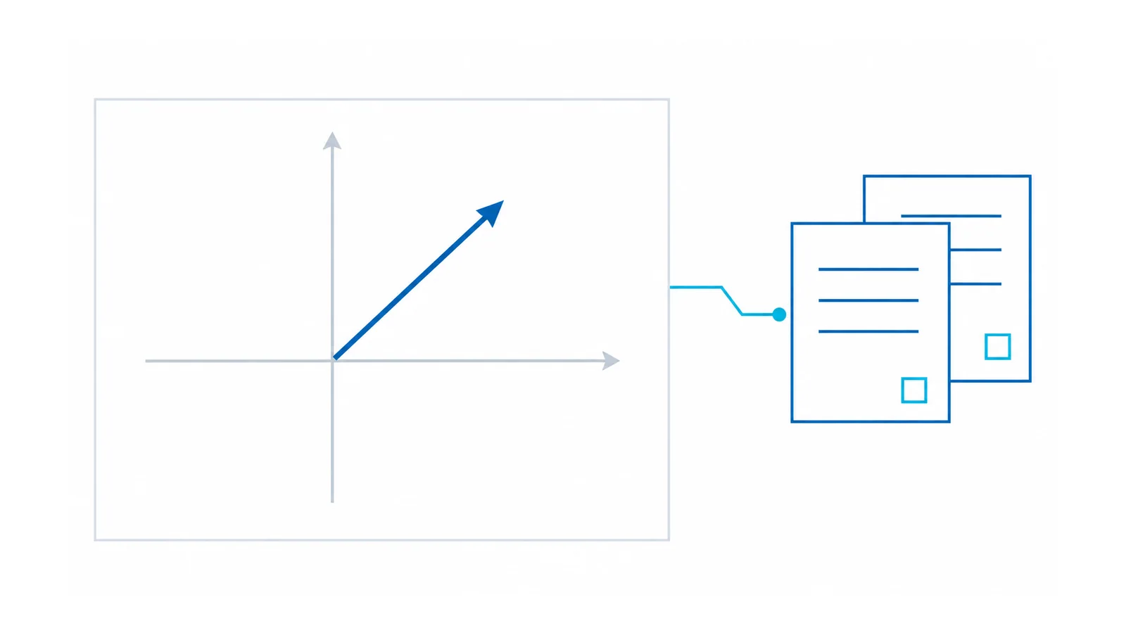
Distance protection compares an apparent loop impedance derived from voltage and current phasors with a defined operating characteristic. A useful calculation must identify the fault loop, line-impedance data, primary or secondary ohm basis, current-transformer (CT) and voltage-transformer (VT) ratios, and ground-current compensation convention. A reach percentage without those definitions is not a defensible relay setting.
This reference explains conventional phasor-based line distance calculations for effectively earthed, three-phase alternating-current (AC) networks. The worked example assumes an uncompensated, uniform line. It does not select a live relay’s zone reaches, time delays, teleprotection logic or test settings. Series compensation and other special applications need their own methods and evidence.
The public scope of IEC 60255-121:2014 covers functional and performance evaluation of distance protection, including impedance-plane characteristics, phase selection, directionality, timing and instrument-transformer requirements. Product performance evaluation is not a completed network application study.
Use phasor loop quantities, not an arbitrary V/I ratio
Let V_A and V_B be phase-to-neutral voltage phasors, and I_A, I_B and I_C the corresponding phase-current phasors at the relay’s measurement location. The quantities must share a consistent reference and primary or secondary basis.
For an A–B phase loop, a conventional apparent impedance is:
Z_AB = (V_A − V_B) / (I_A − I_B)
For an A–earth loop using residual-current compensation:
Z_AG = V_A / (I_A + k_res × I_res)
where:
- I_res = I_A + I_B + I_C = 3I_0;
- I_0 is the zero-sequence current phasor;
- k_res = (Z_0 − Z_1) / (3Z_1);
- Z_1 and Z_0 are the positive- and zero-sequence line impedances on the same basis.
EPRI’s OpenDSS distance-relay documentation presents these loop equations and explicitly warns that its simplified model lacks important protection-design features. Use the equations to understand the quantity being calculated; do not treat that simulation model as a relay-application approval.
Phasor subtraction is essential. Subtracting root-mean-square (RMS) magnitudes is not equivalent to subtracting complex voltages or currents. A magnitude-only calculator can discard the angle that determines a point’s position on the resistance–reactance plane.
Calculate the line impedance on a named base
For a uniform line with positive-sequence impedance per unit length z_1 and length L:
Z_1,line = z_1 × L
Use compatible units: Ω/km multiplied by km yields Ω. Resistance and reactance remain separate real and imaginary components. If the line contains materially different sections, sum their impedances on the same basis rather than using one arbitrary average.
Record the origin and assumptions of positive-, negative- and zero-sequence data. Ground-return conditions, parallel circuits and mutual coupling can affect the ground-loop application. A phase-impedance calculation does not establish the correct earth-loop compensation by itself.
Also identify which line segment each zone is meant to cover and which operating conditions the application study includes. The distance element measures electrical impedance, not geographic distance directly. Fault resistance, infeed and network configuration can change the apparent impedance seen at one terminal.
Convert primary ohms to secondary relay ohms correctly
Define the instrument-transformer ratios as:
CTR = I_primary / I_secondary
VTR = V_primary / V_secondary
Both are dimensionless. Use corresponding voltage quantities in the ratio: do not mix line-to-line primary voltage with phase-to-neutral secondary voltage.
Since V_secondary = V_primary / VTR and I_secondary = I_primary / CTR:
Z_secondary = Z_primary × CTR / VTR
The inverse conversion is:
Z_primary = Z_secondary × VTR / CTR
This follows directly from the voltage/current definitions. Write the ratio definitions beside the calculation rather than remembering an unexplained conversion multiplier.
Some relays accept primary line data and perform conversion internally. Others require secondary-ohm entries, and a test set may expose a further primary/secondary display choice. Confirm the actual setting and test conventions. Entering a converted number into a field that already performs conversion can double-convert the reach.
OHELE’s CT and VT selection guide covers the related measurement requirements. Correct ratio arithmetic does not prove suitable accuracy or transient performance.
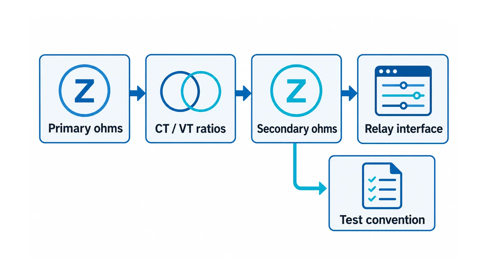
Worked example: line data, reach quantity and relay-ohm conversion
All inputs below are hypothetical teaching values, not an actual line or recommended protection setting.
| Input | Assumed value | Meaning |
|---|---|---|
| Line length, L | 40 km | Uniform uncompensated line |
| Positive-sequence impedance, z_1 | 0.10 + j0.40 Ω/km | Series impedance per kilometre |
| CT ratio | 800 A / 1 A | CTR = 800 |
| VT ratio | 132,000 V / 110 V | Corresponding voltage quantities, VTR = 1,200 |
| Illustrative reach multiplier, m | 0.70 | Chosen solely to demonstrate multiplication and conversion |
The total primary positive-sequence line impedance is:
Z_1,line = 40 × (0.10 + j0.40) = 4 + j16 Ω
An illustrative impedance quantity at the chosen multiplier is:
Z_reach,primary = 0.70 × (4 + j16) = 2.8 + j11.2 Ω
On the secondary basis:
Z_reach,secondary = (2.8 + j11.2) × 800 / 1,200
Z_reach,secondary ≈ 1.867 + j7.467 Ω
The ratio multiplier is dimensionless, so the result remains in ohms. Converting the unrounded result back with 1,200/800 returns 2.8 + j11.2 Ω. A round-trip check is useful for catching a reversed CT/VT multiplier.
The selected 0.70 is not a recommendation for Zone 1. It does not establish a mho or quadrilateral characteristic, resistive reach, directional behavior, operating delay, security margin or coordination with the remote end. Do not copy it into a relay merely because the arithmetic is correct.
Resolve the factor-of-three ground-loop trap
Suppose, for the same hypothetical line, the assumed zero-sequence impedance is:
Z_0,line = 12 + j48 Ω = 3Z_1,line
Then the compensation multiplier for a denominator using residual current is:
k_res = (Z_0 − Z_1) / (3Z_1) = 2/3
If another interface defines the denominator as I_A + K_0 × I_0, rather than I_A + k_res × I_res, the equivalent multiplier is:
K_0 = (Z_0 − Z_1) / Z_1 = 2
The expressions are equivalent because I_res = 3I_0. Copying 2/3 into the second convention would not represent the same compensation. Nor should the notation “k0” be assumed to mean one convention across every relay, calculation sheet and test set.
In a real network, the compensation factor is generally complex. Preserve its magnitude/angle or real/imaginary representation as the actual interface requires. The example’s real factor results from the deliberately proportional assumed impedances; it is not a claim that zero- and positive-sequence impedances always have the same angle.
Before release, compare the stated equation and current definition in the relay documentation with the study calculation and test setup. A coefficient name without its equation is incomplete evidence.
Arithmetic is one gate; the application study is another
The IEEE PSRC report on overreaching distance relays discusses application security, including how load can enter a distance characteristic. Normal or emergency loading is not automatically outside the operating region because it is not a fault. Reach, characteristic shape, load encroachment and dynamic behavior need coordinated review.
Use a calculation-to-test register rather than a list of generic zone percentages:
| Review area | Evidence required before settings release |
|---|---|
| Line and network model | Validated sequence impedances, line sections, relevant mutual coupling and credible source/configuration cases |
| Measurement chain | CT/VT ratios, polarity, wiring, accuracy and relevant transient-performance assumptions |
| Impedance convention | Primary/secondary basis, complex representation and interface conversion rules |
| Ground loops | Residual or zero-sequence current definition, compensation equation and applicable coupling treatment |
| Protection application | Reach, characteristic, directionality, delay, fault-resistance/infeed cases, loading and required scheme interfaces |
| Functional verification | Approved tests of expected operation and restraint, supervision, enabled logic and actual trip outputs |
Choose tests that can expose an incorrect ratio, compensation convention or enabled loop, not only tests at one convenient interior point. Expected operate/restraint results and timing must come from the accepted study and actual relay behavior. If voltage supervision blocks the function, or a permissive signal changes the trip logic, that behavior belongs in the acceptance evidence too.
Keep commissioning and restoration under control
The CT installation and testing workflow explains why current circuits require controlled handling; a live CT secondary must not be opened. Likewise, voltage circuits, test switches and enabled trip outputs require the approved isolation and test plan.
An impedance element that asserts is not proof that the intended breaker clears the fault. Verify the actuation boundary through the trip-circuit checklist and restore every test link, block and setting under configuration control. Only authorized, qualified personnel should perform those tasks.
Release the calculation when its data, units, ratios, loop equations and conversions are independently checked. Release actual settings only after the protection application, tests and restoration record are accepted. Keeping those two decisions separate prevents correct arithmetic from becoming an unjustified operating instruction.