
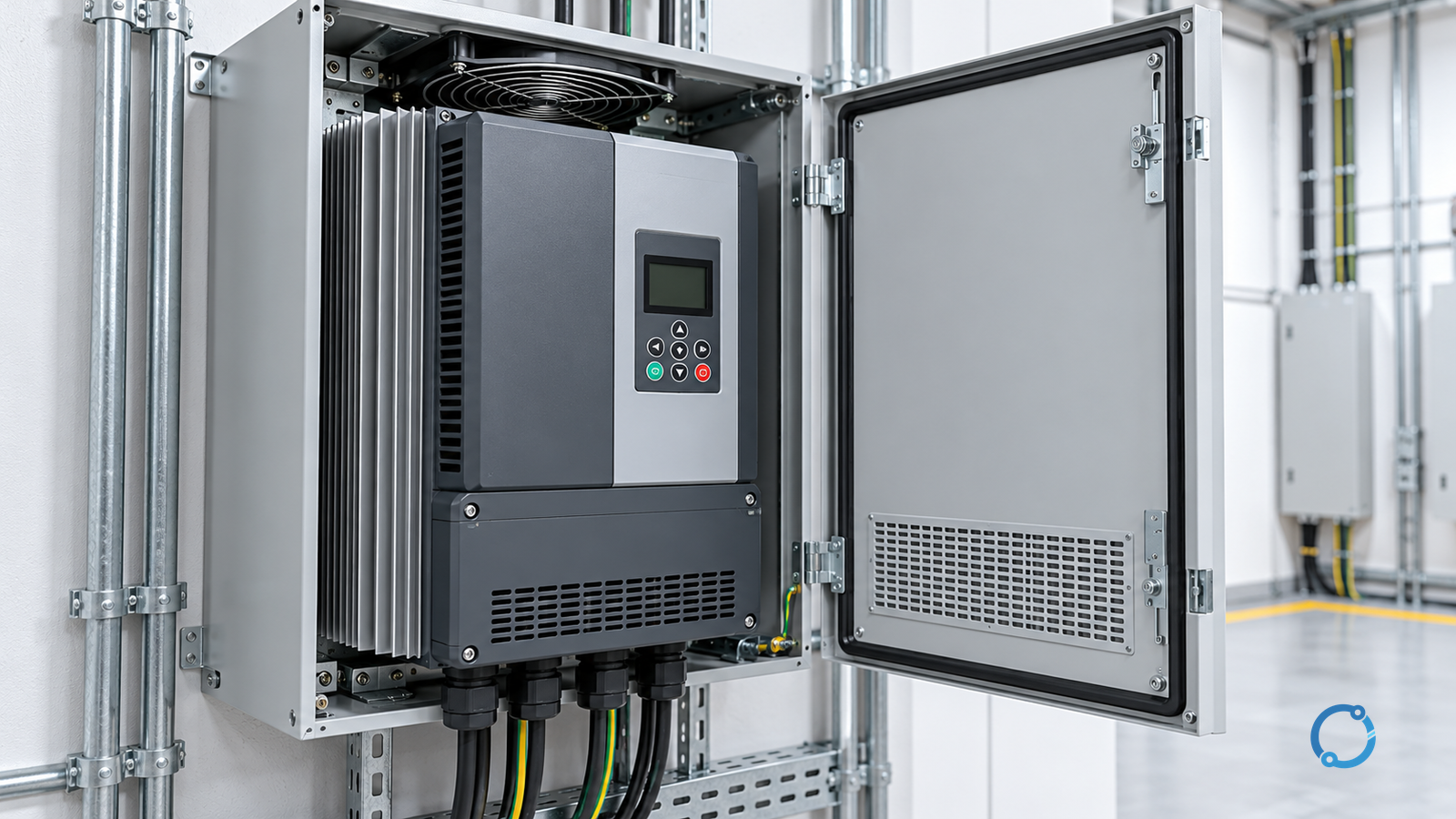
A useful drive maintenance visit produces evidence, not just a cleaned cabinet. The sequence matters as much as the checklist: isolate and verify first, confirm the DC bus is at a safe level, then work outward from the drive’s environment to its power connections, its motor circuit and finally its control settings and records.
That order is deliberate. Many drive problems originate outside the power stage – in a blocked heatsink, a degraded cabinet fan, a loose lug, a damaged motor cable or a parameter that no longer matches the machine. Checking the power stage first, before the cooling and cable interfaces, tends to confirm a conclusion instead of testing it.
The scope here is a low-voltage AC drive installed in an industrial enclosure. Safety requirements for drive systems are addressed in IEC 61800-5-1:2022; general requirements and ratings in IEC 61800-2:2021; EMC in IEC 61800-3:2022. This article does not replace the installed drive’s manual, the site’s lockout procedure, or the judgement of a qualified person.
Only qualified personnel working under an approved site procedure should perform the electrical inspection or tests described here. Before the outage, assemble the installed drive manual, approved limits, parameter backup and existing trip/temperature records. Collect any additional operational data only through an authorized guarded process; opening a cabinet requires its own work controls.
Step zero: isolation and stored energy
Before any inspection inside the enclosure, the drive must be isolated under the site’s hazardous-energy procedure. In US general industry that framework is OSHA 1910.147 for control of hazardous energy and OSHA 1910.333 for de-energization and verification. Other jurisdictions have equivalent requirements, and local rules govern.
An open supply breaker alone does not establish a safe-to-work state. The DC bus holds stored energy in its capacitors, and the discharge time depends on the drive’s design, the bus voltage and the connected load. The manufacturer’s manual states the waiting time and the points to measure; that instruction is the authority, not a rule of thumb carried between sites.
Three checks belong in the isolation step:
- Confirm the correct drive is isolated. Multi-drive panels and shared DC buses can leave a unit energized from another source.
- Wait the manufacturer’s stated time. Do not shorten it because the drive is small or because the visit is running late.
- Verify at the specified terminals with a correctly rated instrument. A qualified person must verify the relevant supply, bus and auxiliary circuits using the specified test points and instrument procedure, including checks of instrument operation. A dark indicator is insufficient. Address shared buses, backfeeds and possible motor-generated voltage; secure the mechanical load as the approved procedure requires.
Only after the bus is verified at a safe level does the physical inspection begin. If the measurement does not agree with the expected discharge, stop and treat the drive as energized.
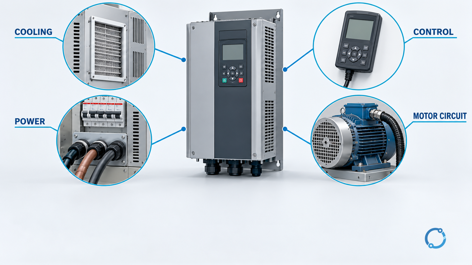
Layer 1: environment and thermal path
Start with the enclosure and cooling path. It is a useful place to identify loss of the intended cooling and contamination control.
Cabinet intake and exhaust. Confirm filters are present, correctly seated and not collapsed. A filter that has been removed because “it kept clogging” changes the enclosure’s thermal and contamination behaviour.
Fan condition. Under the verified isolation, inspect accessible fan assemblies for damage or blockage only as the manual permits. Use existing alarm history or a separate authorized guarded operational check for speed and noise. Do not energize an open drive to complete an inspection item.
Heatsink and ducts. Inspect the heatsink fins for compacted dust, and check that the airflow path is not blocked by added wiring or a mounting plate. Compressed air is not automatically appropriate; it can drive contamination into the drive and create a static discharge risk.
Enclosure condition. Look for damaged gaskets, missing cover screws, corrosion, water staining and evidence of ingress. The declared ingress protection of the enclosure depends on those details remaining intact.
Ambient conditions. Record the actual ambient temperature near the drive intake, not the room temperature at the door. Drives are often installed at the top of a cabinet where the local temperature is well above the plant average.
Record observations with their date, operating state and comparison basis. Use existing measurements or approved guarded checks for operational data. Do not add energized probing merely to obtain a trend number.
Layer 2: power connections and DC bus
With the drive verified de-energized, inspect the power path.
Supply and motor terminations. Check for discoloration, heat damage, loose strands, corrosion and correct lug seating. Tighten or check torque only when the manufacturer’s maintenance instructions require it, using the specified method and calibrated tool. Do not routinely disturb every connection. A terminal that has been over-tightened is as much a defect as one that is loose, particularly on smaller drives where the terminal block is part of the drive’s thermal path.
DC bus and capacitor condition. Inspect only the parts accessible under the manufacturer’s service procedure; do not dismantle sealed power sections for this checklist. Where accessible, look for bulging, leakage, venting or discoloration. These are visible signs of degradation, not a complete assessment. Capacitor health is better tracked by trended measurements where the manufacturer provides a method, and by recording the drive’s operating hours and thermal history.
Braking components. If a braking resistor or chopper is fitted, check the resistor for discoloration, correct mounting and clear ventilation, and confirm the thermal protection is connected. Relocating or enclosing a resistor changes the conditions that must be checked against its declared rating and installation instructions.
Surge and filter components. Confirm that any input or output filter, reactor or dv/dt filter is still installed as designed and that its terminations are sound. An undocumented bypass changes the installed design and requires engineering review.
The output of this layer is a list of connections verified, values measured and defects found – not a pass/fail opinion.
Layer 3: motor circuit and cable
The motor circuit is where drive problems and motor problems are most easily confused. A drive that trips on overcurrent may be reporting a cable or motor fault accurately.
Cable condition. Inspect the motor cable for mechanical damage, tight bend radius, crushed sections and damage at the gland. Confirm that the cable type is suitable for drive output, including screening where the installation relies on it for EMC.
Screen and earthing. Confirm the screen is bonded at the intended points and that the protective conductor is intact. A screen that has been cut back during a repair changes the EMC behaviour of the whole circuit.
Insulation resistance. Use a qualified person and an approved test plan. Disconnect the drive and other sensitive electronics from the circuit under test as their instructions require; never apply an insulation-test voltage through a connected drive. Select the test voltage and acceptance basis for the motor/cable system, then safely discharge the tested circuit before reconnection. Record temperature and test conditions so trends are comparable.
Motor condition indicators. Record winding temperature history where available, bearing noise, vibration and cooling condition. OHELE’s guide to motor operating temperature diagnosis explains why the drive’s current reading alone does not establish the motor’s thermal state.
Load behaviour. Note any change in the machine’s load, such as a worn bearing, a blocked impeller or a changed product recipe. A drive that appears to be failing may be reporting a genuine mechanical change.
Layer 4: control, parameters and records
The final layer is information, and it is the one that makes the previous three useful.
Parameter backup. Confirm a current parameter set exists and is stored outside the drive. A backup that predates the last commissioning change is a liability. Compare the last approved saved/read-back set with the backup and record differences. Capture powered read-back only through an approved guarded check; do not bypass isolation to access a display or communications port.
Trip history. Use the preserved trip log captured before the outage or an approved guarded read-out after restoration. Do not clear it before recording it. The sequence and timing of trips often identify the layer at which the problem started. Clearing the log at the beginning of a visit destroys evidence.
Control interfaces. Inspect connection condition and shield bonding under isolation. Evaluate analogue signal integrity from existing records or a separate approved operational test; inspect encoder and feedback cables without live access. An intermittent analogue reference can produce speed instability that looks like a drive fault.
Cooling and run-hour counters. Record the drive’s run hours and any accumulated thermal values so that the next visit can compare them.
Documentation. Update the panel schedule, the parameter record and the maintenance log. A maintenance visit that is not recorded cannot be trended, and an untrended drive is maintained by reaction rather than by condition.
Trend triggers, not fixed intervals
Fixed intervals are convenient, but they are not the same as condition-based maintenance. Start from the manufacturer’s maintenance schedule and the site’s required intervals. Adverse conditions may require more frequent checks; any extension needs an approved basis.
The following findings should trigger an engineering review rather than a routine close-out:
- Repeated overcurrent or overvoltage trips with no identified process cause.
- A rising trend in drive temperature or a growing difference between heatsink and ambient temperature.
- Visible capacitor degradation, or a manufacturer-provided health indicator moving in the wrong direction.
- Fan current or speed drift, or recurring filter blockage at the same site.
- Insulation resistance trending down across visits.
- A parameter set differing from the commissioned baseline without an authorized change record.
- Motor cable or screen repairs that changed the EMC arrangement.
The response to these findings depends on the drive family and the process criticality. A reliability review may schedule work for the next outage only after an authorized assessment confirms continued operation is acceptable. Visible electrical damage, failed isolation verification or an unresolved unsafe condition prevents routine return to service. The article cannot set that threshold, but it can insist that the threshold be a recorded decision.
What not to do
Do not reset and restart a repeatedly tripping drive without recording the trip. The trip code and timestamp are the most useful evidence available.
Do not measure the DC bus without confirming the meter’s category rating and the correct measurement points. A meter that is not rated for the bus voltage is a hazard, not a diagnostic.
Do not clean the heatsink with uncontrolled compressed air. It can force contamination into the drive and create static damage.
Do not replace a drive before checking the motor cable and the mechanical load. A cable or mechanical problem can cause a protective trip without a failed power stage.
Do not restore a bypassed filter or reactor without confirming why it was bypassed. The bypass may have been a deliberate response to a compatibility problem that needs a proper solution. OHELE’s guide to harmonic mitigation selection and to VFD sizing against machine loads cover the design-side questions that a maintenance visit should not silently change.
A one-page record that works
The record can be short if it is structured. For each drive, capture:
| Layer | Minimum record |
|---|---|
| Isolation | Isolation point, lock identity, waiting time applied, bus voltage verified |
| Environment | Ambient at intake, filter condition, fan condition, heatsink condition, enclosure condition |
| Power | Terminations checked, values measured, defects found, parts replaced |
| Motor circuit | Cable and screen condition, insulation resistance result, motor indicators |
| Control | Backup compared, trip log recorded, interfaces checked, parameters changed |
| Decision | Next action, owner, date, and the trend data that justified it |
That table is the difference between a maintenance visit and a maintenance record. The visit produces findings; the record makes them usable at the next visit.
Restore only after the release checks
Close defects that prevent safe service before re-energization. Confirm test equipment and temporary connections have been removed, protective conductors and screens restored, covers and guards fitted, ventilation clear and the approved parameter set documented. Have the authorized person release the isolation under the site procedure after checking the area and notifying affected personnel.
A guarded functional run must follow the machine’s approved restart sequence. Check direction, command/feedback, required interlocks and the relevant trips or safety functions using the commissioning plan; a drive run command is not a safety-function test. Record which conditions were tested and stop if a trip repeats, unexpected motion occurs or the observed condition is outside the approved limits.
Conclusion
Drive maintenance is most effective when it follows the energy path and the evidence path at the same time. Isolate and verify, then inspect cooling, power connections, the motor circuit and the control layer in that order. Record what was measured, compare it with the previous visit, and escalate on trends rather than waiting for a failure. The drive’s manual remains the authority for discharge times, torque values and component-specific limits; this sequence tells you what to look for and what to write down.
Sources
- IEC 61800-5-1:2022, drive-system safety scope
- IEC 61800-2:2021, AC drive-system requirements
- IEC 61800-3:2022, EMC scope
- OSHA 1910.147, hazardous-energy control
- OSHA 1910.333, electrical work practices
This is an editorial maintenance-planning sequence. Equipment manuals and approved site procedures supply the actual discharge time, limits, test methods and acceptance criteria. Standard catalogue pages establish scope, not a universal service schedule.