

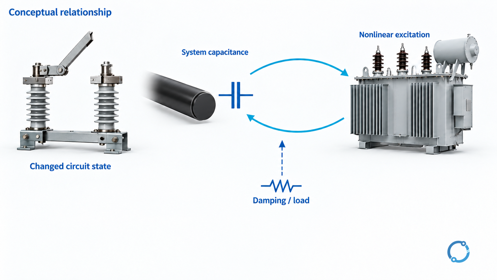
Suspect ferroresonance when a switching event leaves a credible interaction between nonlinear magnetic excitation and system capacitance, particularly under a lightly loaded or unusual phase configuration. Confirm the hypothesis using the actual circuit state, waveform evidence and a suitable transient study. Noise, a damaged VT or one high-voltage reading is not proof of ferroresonance.
This guide covers investigation of transformer and inductive voltage-transformer events in MV systems. It does not reconstruct a named accident or offer a universal damping resistor. The worked scenario below is hypothetical and contains no measured incident data.
Establish a mechanism, not just an event label
In an ordinary linear resonance model, inductance is treated as fixed. A transformer magnetizing branch is nonlinear: its behavior changes with magnetic excitation and saturation. Together with circuit capacitance and limited damping, that nonlinearity can support undesirable oscillation. A single linear frequency calculation cannot establish whether a particular switching state will enter it.
The DOE-sponsored utility modeling report, PDF page 52 describes distribution-transformer ferroresonance involving open phases and system capacitance, including cable-fed configurations. It identifies transformer connection and loading as relevant and points to transient simulation for analysis. These are susceptibility factors, not a rule that every lightly loaded cable-fed transformer will experience ferroresonance.
IEC TR 61869-102:2014 addresses ferroresonance in MV/HV networks with inductive VTs and recognizes other nonlinear inductive components. Its public scope supports investigating the phenomenon beyond a single transformer type. It does not establish a project-specific mitigation value.
Preserve the switching-state evidence
The investigation needs more than the final one-line diagram. Capture the actual sequence, including pole states, fuse conditions, source availability and the time at which each load changed. Preserve relay oscillography, sequence-of-events records and operator logs before resets or configuration changes overwrite them.
Have the responsible specialist identify every relevant capacitance: cables, connected equipment and other network elements that the model requires. Establish the transformer or VT connection, magnetic data, loading and grounding arrangement. Nameplate voltage and cable length alone are insufficient transient-model inputs.
Do not recreate a suspicious switching sequence on energized equipment to “see whether it happens again.” Use the site’s emergency response and approved isolation procedure. Damage, smoke, abnormal pressure or credible sustained electrical distress requires escalation, not a listening experiment. The separate transformer abnormal-noise guide explains why acoustic patterns are clues rather than fault labels.
Use competing hypotheses to guide the next check
This matrix is an editorial investigation framework. Its observations prioritize evidence; none is a standalone diagnosis.
| Observation or known condition | Ferroresonance question | Competing explanation to retain | Next evidence |
|---|---|---|---|
| Event follows a phase-selective switching or fuse change | Did the resulting configuration couple magnetic excitation and capacitance? | Open-phase operation or an unrelated equipment fault | Actual pole/fuse states and topology timeline |
| Disturbance continues after the initial switching instant | Is a sustained nonlinear state credible? | Neutral displacement, source regulation or ongoing fault | Time-resolved voltage/current records and grounding review |
| Transformer or VT is very lightly loaded | Is damping materially different from the studied state? | Normal excitation noise or a measurement issue | Actual load/burden and excitation data |
| Cable or connected network has changed | Has relevant capacitance altered the model? | Other switching-transient or protection changes | As-built capacitance inputs and previous study basis |
| VT readings disagree with other indications | Are the readings valid evidence of primary voltage? | VT fuse, secondary wiring, channel scaling or recorder limitation | Verified measurement chain and independent records |
Distinguish ferroresonance from a short switching transient. Vacuum-breaker current chopping concerns a different mechanism that can also create overvoltage. An SPD or arrester does not by its presence prove that a sustained nonlinear condition has been prevented.
A hypothetical cable-fed transformer investigation
Assume a three-phase cable-fed transformer was lightly loaded when a switching change left an incomplete phase connection. Recorded voltage behavior continued beyond the initial operation, and unusual transformer noise was reported. These facts justify checking a ferroresonance hypothesis, but they do not establish it.
The investigator would first confirm whether the “open” phase was truly isolated in the resulting network and whether the records came from trustworthy voltage channels. Next, the specialist would assemble the cable/network capacitance, actual winding connection, excitation characteristic and losses or loading needed by the model. Missing magnetic data should be an explicit uncertainty, not replaced by an arbitrary linear inductance.
A transient study would test the observed state and credible variations in switching conditions and loading. If the suspected mechanism cannot be reproduced within defensible inputs, retain other explanations. If it can, compare the proposed corrective arrangement against the observed case and other permitted operating states. A model result is evidence within its assumptions, not a substitute for checking the as-built circuit.
The DOE distribution-transformer proposal’s technical discussion notes nonlinear capacitive/inductive interaction and susceptibility of particular distribution-transformer connections. That discussion is technical context from a 2022 proposal, not a current operating mandate or proof about this hypothetical transformer.
Select mitigation against the verified circuit
Possible study directions include changing the permitted switching arrangement, preventing incomplete-phase states, revising the transformer/VT configuration or providing an engineered damping arrangement. Which direction is suitable depends on the mechanism established and the equipment’s approved application.
Do not add a resistor to a VT winding from a generic online value. Its connection, continuous and event duty, heat dissipation, insulation, protection interaction and effect on measurement must be evaluated. Likewise, adding load simply to suppress an observed event is not a verified permanent design.
For inductive VTs, revisit the specified winding functions and burdens using the substation VT selection guide. A mitigation that changes the measurement boundary also needs protection and metering review.
Define the release evidence
Before re-energization, the responsible team should have a resolved event hypothesis or a clearly controlled remaining risk, a documented corrective design, approved inspection/test results and a verified operating-state restriction where required. Record study assumptions, equipment damage assessment, protection implications and the as-left configuration.
If waveform quality, switching state or magnetic data remains unresolved, say so. A useful investigation concludes which mechanism is supported, which alternatives were excluded and what evidence permits restoration. It does not conclude “ferroresonance” merely because that label seems to explain several symptoms.