
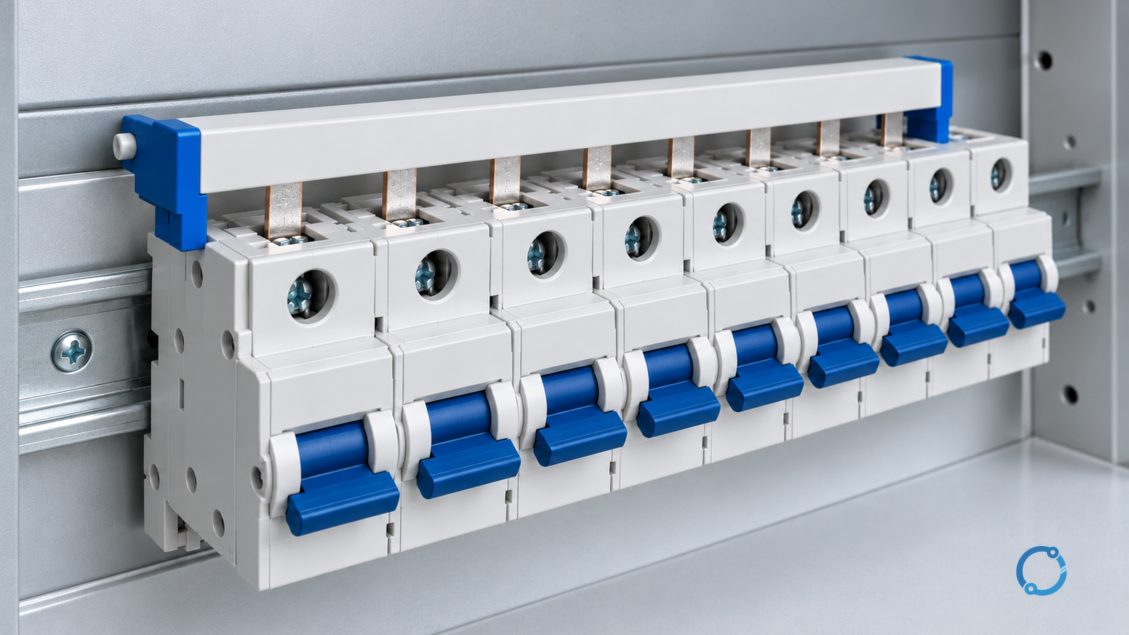
Use a comb busbar when the breaker family, pole pitch, pole count and current rating are fixed, the busbar is declared for that exact breaker, and the row will not be reconfigured. Consider jumper wiring when individual conductor routes are necessary and every terminal is approved for the proposed conductor count and preparation. Mixed devices still need assembly-level compatibility evidence; jumper wires do not authorize mixing unverified breaker families.
That is the whole decision in one paragraph. The rest of this article explains why the choice keeps turning into an argument, and what evidence settles it. Both methods are legitimate. The important review is whether the chosen distribution method matches the actual terminals, loading and verified assembly design.
The scope here is a DIN-rail row of miniature circuit breakers (MCBs) inside a low-voltage assembly. The assembly itself is verified under a standard such as IEC 61439-1:2020, which is the framework that makes internal wiring and component selection part of one verification. North American panelboards follow a different route under UL 67. The comparison dimensions are similar; the compliance evidence is not interchangeable.
What the two methods actually are
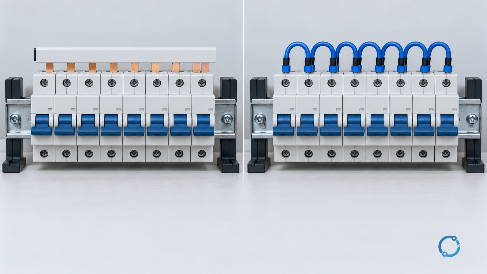
A comb busbar is a rigid conductor with a row of teeth or prongs that enter the supply terminals of adjacent breakers. A single-phase comb feeds adjacent devices on the same phase; multi-phase combs use a declared repeating phase sequence. The supply pattern must match the breaker pole arrangement. It replaces a series of short conductor loops with a shaped copper part.
A jumper wire is an insulated conductor run from one breaker terminal to the next, or from a feeder terminal to each breaker. Each connection is made with a conductor, a prepared end and a terminal screw or cage.
The physical difference produces the decision difference. A busbar is one part with many contacts. Jumper wiring uses individual conductors with a termination at each end. That changes assembly time, inspection effort, configurability, and the way a single defect propagates through the row.
Fixed-dimension comparison
The table evaluates both methods on the same dimensions. Neither column is “better” in general; each cell describes a tendency that must be confirmed for the actual assembly.
| Dimension | Comb busbar | Jumper wire | What to verify |
|---|---|---|---|
| Assembly time | Fewer operations; one part seats across many devices | Two terminations per jumper, repeated along the row | Labour rate, row length, access |
| Repeatability | Contact position set by the busbar geometry | Contact quality depends on each termination | Torque record and inspection sample |
| Breaker compatibility | Must match terminal type, pitch, pole count and family | Flexible routing; mixing still requires verified assembly compatibility | Device, terminal and assembly approval |
| Current rating | Check each segment for the declared feed position and loading | Each segment must carry all downstream loads that pass through it | Segment current, diversity, terminal limits and upstream protection |
| Short-circuit withstand | Depends on the busbar and the supported breaker combination | Depends on conductor and terminations | Assembly verification and device coordination |
| Reconfiguration | Removing or adding a device may require a different busbar | Straightforward to modify | Change-control procedure |
| Space | Compact; reduces conductor clutter in the terminal area | Requires bending room and wiring space | Wireway and bend radius |
| Inspection | Check seating and every clamping point as instructed | Check each termination and loop-through arrangement | Safe access and the specified maintenance method |
| Fault propagation | Feed-point or busbar damage can affect multiple circuits | An upstream jumper or shared terminal failure can affect every downstream tap | Fault location, loop-through arrangement and isolation scope |
| Access protection | Insulation, end caps and vacant teeth need review | Terminal shrouds and conductor entries need review | Declared protection for the complete assembly |
When a comb busbar is the stronger choice
A comb busbar is usually the better fit when all of the following are true:
- The row uses one breaker family with a consistent pole pitch.
- The number of poles and the phase arrangement are fixed at design release.
- The total current through the busbar and the current at each tap are both inside the busbar’s declared application.
- The busbar is declared by its manufacturer for that breaker family, not merely dimensionally similar.
- The assembly’s short-circuit verification supports the combination.
- The enclosure and cover arrangement allow the busbar to be installed and inspected without strain on the breaker terminals.
When those conditions hold, the busbar removes a large number of terminations from the build. This can reduce conductor-end preparation and routing work. It does not eliminate inspection of each breaker clamp. It also produces a tidier terminal area, which makes later inspection faster.
The conditions are strict because the part is not generic. A busbar with the right pitch but the wrong tooth profile, the wrong number of poles, or a rating declared for a different breaker series is not an equivalent part. Dimensionally similar is not electrically equivalent.
When jumper wiring is the stronger choice
Jumper wiring can suit a permitted arrangement needing individual routes:
- Devices of different widths share a rail within a verified assembly arrangement.
- Tap currents differ enough that a single busbar rating is the wrong abstraction.
- The design must accommodate additions or re-arrangement after commissioning.
- The intended phase/neutral sequence or switched-neutral arrangement is not covered by the available busbar system.
- The available busbar cannot be matched to the installed devices with documented ratings.
- The assembly is a one-off where tooling and lead time for a specific busbar are impractical.
Fault consequences depend on location in either method. A poor comb feed connection can interrupt the whole row, while a poor loop-through jumper can remove every downstream circuit. Evaluate the actual path and redundancy rather than assuming jumper faults stay local.
Installation differences that change the outcome
The methods differ in where the work is concentrated.
With a comb busbar, most of the quality is built into the part. The installation risk sits in three places: seating the teeth fully into the correct terminals, avoiding mechanical strain on the breaker bodies, and tightening the supply connection to the declared torque. A busbar that is forced, tilted or partially seated can look installed while making poor contact. On many breaker systems, each tooth is clamped by an individual screw terminal; others use a different approved contact arrangement. Inspect and tighten every connection as its instructions require, including the feed terminal.
With jumper wiring, the quality is built at every termination. Conductor preparation, ferrule or lug selection, insertion depth, screw torque and strand containment all matter, and they matter at both ends of every jumper. This is why jumper wiring takes longer and why inspection has to sample more points. OHELE’s guide to MCB tripping causes and diagnostic checks shows how a loose or overheating termination can present as a breaker problem rather than a wiring problem.
Both methods share the same boundary condition: the breaker terminal is only rated for the conductor or busbar pin it was evaluated with. A tooth and a conductor may share a terminal only when that exact combination is declared acceptable. Similarly, loop-through jumpers can put two conductors in one terminal; confirm the permitted count, types, sizes and preparation. Otherwise use an approved distribution block or a separately evaluated feed arrangement.
The rating question that decides most disputes
Most comb busbar arguments are really about current. A busbar has a current rating, and a row of breakers has a total load. Those are not the same quantity.
Three currents have to be separated. In a daisy-chain jumper row, early segments carry the combined demand of the taps downstream; sizing every jumper for only one breaker can overload those segments. Check conductor capacity, terminal capacity, grouping and upstream protection for each segment.
The three quantities are:
- The assembly or feeder current that the busbar carries before it splits.
- The current through each tap, set by the breaker and its downstream load.
- The busbar’s declared rating for the specific installation conditions, including how it is mounted and how many poles are fed.
Do not use the sum of breaker handle ratings as a load calculation. Establish the permitted design current and diversity, then check the busbar segment carrying the highest current. End feeding, center feeding and multiple feeds can produce different segment duties; only use arrangements covered by the system instructions.
For the same reason, a busbar’s short-circuit performance cannot be inferred from its cross-section. The assembly’s verification and the breaker combination determine what the row can withstand. OHELE’s comparison of panel busbars and block-and-cable distribution covers the wider distribution architecture, and the article on busbar behaviour under short-circuit stress explains why the mechanical duty is part of the same question.
Inspection, change control and the life of the row
The two methods age differently.
A comb busbar is stable until someone changes the row. Adding a breaker of a different family, replacing a device with a revised terminal geometry, or inserting a component that interrupts the pitch turns a validated arrangement into an unmatched one. The change may be physically possible and still be electrically unsupported. Good change control therefore treats the busbar as a matched assembly item, not as a reusable strip.
Jumper wiring adds termination points that can be disturbed or damaged. Inspect for condition changes and follow the connection manufacturer’s maintenance instructions. Do not impose a universal re-torque routine: some connections need no periodic retightening and excess tightening can damage them. Provide enough wiring space for safe inspection. OHELE’s guidance on DIN-rail space and terminal blocks is relevant here: a row that cannot be inspected comfortably will not be inspected properly.
A decision sequence that holds up
Work through the questions in order and stop at the first disqualifying answer.
- Is the breaker row fixed in family, pitch and pole count? If no, first verify whether the mixed arrangement is permitted at assembly level; then assess approved wiring or another distribution system.
- Is there a busbar declared for that exact breaker family? If no, do not substitute a dimensional match.
- Are the busbar’s current and short-circuit ratings valid for this arrangement? If not established, the busbar is not yet a design decision.
- Can the assembled row be inspected and the supply connection torqued? If access is poor, the theoretical advantage of the busbar disappears in practice.
- Will the row change during its life? If yes, weigh reconfiguration cost against the assembly savings.
- Does the chosen method still satisfy the assembly verification? If this cannot be answered, the method is not yet selected.
Conclusion
A comb busbar is a matched part that rewards a stable, repeated row. Jumper wiring is a flexible method that rewards good termination discipline and accessible inspection. Choose the busbar for a fixed, compatible, well-supported row; choose jumpers for mixed or changeable rows, or where no busbar can be matched with documented ratings. In both cases the deciding evidence is the same: the breaker family, the current path, the short-circuit support and the ability to inspect what was built.
Sources
- IEC 61439-1:2020, assembly requirements
- IEC 60898-1:2015, circuit-breaker product scope
- UL 67, panelboard scope
The comparison is an editorial design-review framework. Product terminal instructions and verified assembly data determine suitability; catalogue scope pages do not establish a comb or jumper rating.