
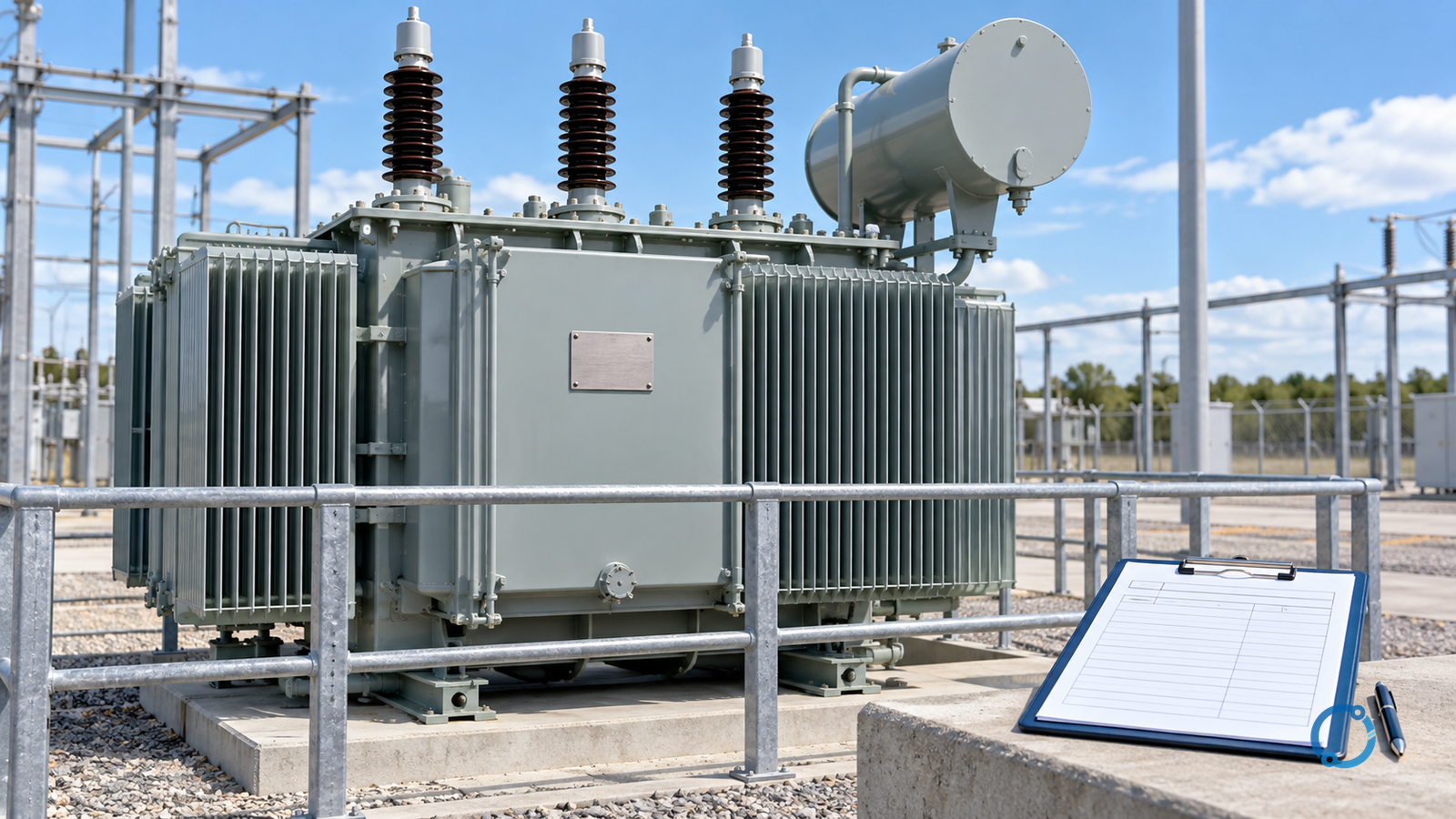
Transformer percent impedance is not a ready-made short-circuit current. It is one branch characteristic expressed on a particular power and voltage base. The defensible first step is therefore to preserve the nameplate or test-report basis, convert that impedance to a clearly labeled per-unit or ohmic value, and only then combine it with the rest of the network.
That distinction matters in reviews. Two calculations can quote the same transformer percentage and produce different results because one used a different study base, confused line-to-line with phase voltage, or paired an ohms value with the wrong winding. The arithmetic may look plausible while the model is no longer comparable with adjacent branches.
This reference article supplies a compact, auditable conversion workflow for a balanced three-phase transformer branch. It does not reproduce IEC equations for every transformer construction or fault type, select protection, or approve equipment. IEC 60909-0:2026 provides the procedural context for short-circuit-current calculation in low- and high-voltage three-phase AC systems at 50 Hz or 60 Hz; a complete study must use the applicable system model and standard rather than this educational conversion alone.
Answer the branch question before calculating
Write one sentence that defines what the calculation is meant to prove:
For transformer T-01, convert the stated percent impedance on its nameplate bases into a transformer branch suitable for the [named study base and fault location], while identifying every source and model assumption that remains outside this branch.
The sentence prevents three common category errors:
- treating the transformer impedance as the total system impedance;
- calculating a current at a point that the transformer branch does not reach;
- using the resulting current to approve a breaker, cable or protection setting without a complete study.
Record the transformer identity, winding connection, rated power, rated voltages, tap position, impedance source and test basis in the same calculation record. A transformer with a different tap, parallel unit, grounding arrangement or operating configuration can present a different network model even when the nameplate percentage is unchanged.
Keep three quantities separate
Transformer impedance appears in reports in forms that look similar but answer different questions.
| Quantity | What it states | What must accompany it |
|---|---|---|
Percent impedance, often written Z% |
A voltage-drop ratio at rated current, conventionally expressed on the transformer’s base | Rated power and voltage basis, winding and tap reference, measured or guaranteed source |
Per-unit impedance, z_pu |
The same ratio in dimensionless form | The base to which the per-unit value belongs |
Ohmic impedance, Z_ohms |
An impedance value in ohms | Which winding, voltage base and frequency context the value refers to |
A percentage without a basis is an incomplete data item. A per-unit value without a base is ambiguous. An ohms value without a winding reference can be attached to the wrong side of the transformer.
The conversion is straightforward once the basis is explicit:
z_pu,own = Z% / 100
This identity is appropriate when the percentage and the per-unit base refer to the same transformer rating. It does not say that every short-circuit study should use the transformer’s own base. It creates a starting value that can be moved deliberately to the study base.
Record the transformer base
Use the transformer nameplate or verified test report rather than an unlabeled database entry. The minimum record should include:
- permanent equipment identifier;
- rated power
S_Nand its unit; - rated line-to-line voltages on both windings;
- winding connection or phase relationship where relevant to the model;
- rated frequency;
- impedance percentage and the report or nameplate from which it came;
- whether the value is at the principal tap or another tap;
- tolerance, measurement condition or guaranteed basis if stated;
- transformer quantity and whether units operate in parallel.
For a balanced three-phase calculation, the transformer base impedance is:
Z_B,transformer = V_LL,N² / S_N
Here, V_LL,N is a line-to-line voltage in volts and S_N is three-phase apparent power in volt-amperes. Using kilovolts and megavolt-amperes together is acceptable only if the units are handled consistently and the result is still recognized as ohms.
The voltage base belongs to the side of the transformer being represented. A value in ohms calculated on the secondary side should not be pasted into a primary-side network branch. The same magnetic branch has different ohmic expressions on the two sides while its per-unit value can remain comparable when the bases are chosen consistently.
Convert percent impedance to ohms step by step
Start with the transformer’s own base. Then:
Z_ohms,N = (Z% / 100) × (V_LL,N² / S_N)
The result refers to the winding whose line-to-line rated voltage was used. State that winding next to the number.
A transparent numeric example
This is a synthetic calculation, not a transformer recommendation. Suppose a fictional transformer has:
S_N = 1,000 kVAor1,000,000 VA;V_LL,N = 400 Von the low-voltage winding;Z% = 5.0at that rating and tap.
First form the per-unit value:
z_pu,own = 5.0 / 100 = 0.05
Then calculate the low-voltage base impedance:
Z_B = 400² / 1,000,000
Z_B = 0.16 ohm
Multiply the per-unit value by the base impedance:
Z_ohms,LV = 0.05 × 0.16
Z_ohms,LV = 0.008 ohm
Record the answer as approximately 0.008 ohm on the 400 V winding at the stated tap, not as 0.008 ohm without qualification.
Now calculate the transformer’s own rated low-voltage current:
I_rated,LV = S_N / (√3 × V_LL,N)
I_rated,LV = 1,000,000 / (√3 × 400)
I_rated,LV ≈ 1,443 A
This current is a reasonableness reference for the transformer branch. It is not a calculated short-circuit current, and it is not a breaker rating or a protection setting.
Change to a study base without losing the trail
A project may use a common base rather than each transformer’s own rating. For a balanced three-phase per-unit system:
z_pu,new = z_pu,old × (S_new / S_old) × (V_old / V_new)²
The formula has two different effects:
- the power-base ratio changes the per-unit impedance inversely with base apparent power;
- the voltage-base ratio changes it with the square of voltage.
For the example transformer, suppose an educational study uses a fictional S_new = 10 MVA power base and the same V_new = 400 V voltage base:
z_pu,new = 0.05 × (10 / 1) × (400 / 400)²
z_pu,new = 0.50 pu
The transformer appears as 0.50 pu on the 10 MVA base. That is not a claim that it is a high-impedance transformer. The number belongs to a larger power base and must be read together with the study convention.
If the voltage base also changes, repeat the ratio exactly. Do not discard the voltage term because it happens to be one in a particular example. A review should be able to reconstruct every unit, denominator and source of each base.
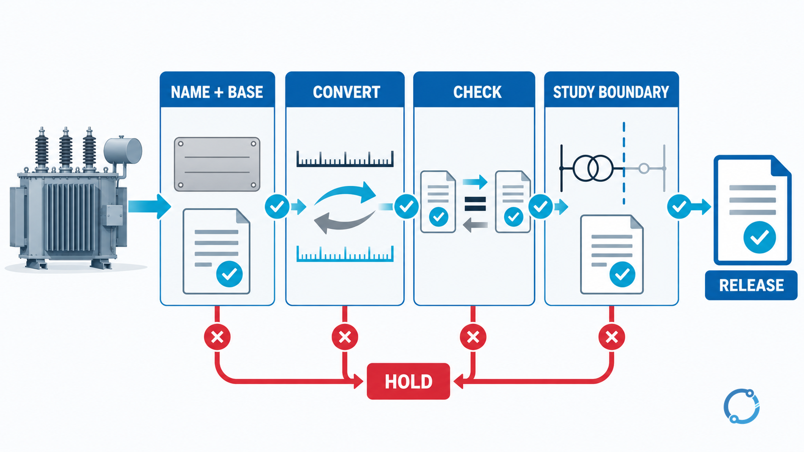
Use the rated current and ohms values as cross-checks
Two checks catch many base and unit errors.
Check 1: scale against transformer rating
On the transformer’s own base, a simplified educational current expression for an ideal source connected directly to the transformer is approximately:
I_fault,idealized ≈ I_rated / z_pu
Using the earlier values gives:
I_fault,idealized ≈ 1,443 / 0.05
I_fault,idealized ≈ 28,860 A
This number is deliberately called idealized. It assumes the transformer branch is fed by an infinite source and ignores upstream impedance, fault point, voltage factor, load current, transformer behavior and the full short-circuit calculation procedure. It is useful only for checking whether a spreadsheet produced a result of the expected broad scale.
If a study output is many orders of magnitude away from this idealized branch reference, inspect the bases before accepting the result. Do not turn the reference into a design value.
Check 2: move through bases in both directions
Starting with z_pu,new = 0.50 pu on a 10 MVA base, convert back to the 1 MVA transformer base:
z_pu,own = 0.50 × (1 / 10) × (400 / 400)²
z_pu,own = 0.05 pu
The return to 0.05 pu proves the arithmetic is reversible. If it does not return, one base ratio or unit conversion is wrong.
For an ohms cross-check on the new power base, recalculate the study base impedance:
Z_B,new = 400² / 10,000,000
Z_B,new = 0.016 ohm
Then:
Z_ohms = 0.50 × 0.016 = 0.008 ohm
The ohms value matches the transformer’s own-base result because the voltage base did not change. This is a consistency check, not permission to mix the two per-unit bases in the same branch list.
Separate the transformer branch from the complete network
A short-circuit calculation is a network problem. The transformer impedance is only one element between a source and a fault location.
For a defensible study, identify at least:
- upstream source and its fault contribution model;
- generator, motor or converter contributions required by the governing method;
- cables, busbars, reactors, transformers and other series elements;
- fault type and fault location;
- system topology and switching state under consideration;
- pre-fault voltage and calculation factors required by the applicable method;
- transformer tap, parallel operation and grounding conditions;
- time domain: initial symmetrical, peak, breaking or another required value;
- treatment of minimum and maximum cases.
The same transformer branch may be reused only if those study inputs remain compatible. A maximum-case model for equipment withstand and a minimum-case model for protection operation can use different assumptions and require different outputs.
The official scope of IEC 60909-0:2026 states that its procedure applies to three-phase AC systems at low and high voltage at 50 Hz or 60 Hz, while systems at highest voltages of 550 kV and above with long transmission lines are outside that document’s scope. That is a standards scope boundary, not a claim that every fault study below 550 kV is identical.
Distinguish the calculation from equipment proof
A transformer percentage can contribute to a short-circuit model without proving anything about the transformer’s ability to withstand a short circuit. IEC 60076-5:2006 addresses the ability of power transformers to withstand short circuits. Its existence does not mean that any calculated fault current within a spreadsheet has been compared with the transformer’s demonstrated or specified withstand capability.
Keep three reviews separate:
- Model review: are the base, branch and network assumptions correct?
- Equipment review: can the transformer and associated equipment withstand the relevant fault duty?
- Protection review: does the protection detect and clear the fault within the required time and coordination?
The same calculated current can be inputs to those reviews, but it does not complete them. Cable heating, busbar mechanical forces, breaker breaking capacity, relay reach, arc-flash assessment and protective-device discrimination may each require additional methods and checks.
The transformer kVA rating basis is useful when the model requires a clear distinction between nameplate rating and operating load. For protection context, the differential relay settings workflow owns a different decision path; a transformer branch calculation should not be substituted for that setting study.
A reviewable calculation record
Use a compact record that another engineer can reconstruct without asking which spreadsheet cell was intended.
| Field | Record |
|---|---|
| Equipment | Tag, serial number and transformer type |
| Source item | Nameplate, routine test report, design calculation or other controlled document |
| Rating base | S_N, V_LL,N, frequency, winding and tap |
| Impedance | Z%, tolerance if available, and whether it is measured or guaranteed |
| Own per unit | z_pu,own = Z% / 100 |
| Own base impedance | Z_B = V_LL,N² / S_N, with units |
| Own ohms | Ohmic value and the winding to which it applies |
| Study base | S_new and V_new, with explicit units |
| Converted value | z_pu,new or study-base Z_ohms |
| Reverse check | Converted value returned to the own base |
| Rated-current check | Formula, inputs and broad magnitude comparison |
| Network use | Fault point, topology and included or excluded sources |
| Remaining limitation | Study standard, unmodeled data and reviewer |
This is not a bureaucratic form. It is the shortest way to prevent a future reader from treating a convenient decimal as a property of the transformer alone.
Review the calculation before it leaves the sheet
Before handing a transformer branch to another person or model, ask:
- Does the transformer identifier on the data sheet match the one in the calculation?
- Are power and voltage bases stated with units and attached to the correct winding?
- Is the percentage at the modeled tap and operating configuration?
- Does the per-unit value return to its original value when converted back?
- Does the ohms value from the own base match the ohms value from the study base?
- Is the rated current calculated with the same transformer base?
- Has the idealized branch current been labeled as a check and not as a complete result?
- Are upstream sources, parallel paths and fault location explicit?
- Is the calculation method appropriate to the required fault current and system voltage?
- Have equipment withstand and protection performance been reviewed separately?
If any answer is unknown, the model may still be useful for exploration, but it is not ready to support a consequential decision.
What the final answer should say
A transparent conclusion resembles this:
Transformer T-01 has a stated impedance of 5.0 percent on 1.0 MVA and 400 V at the modeled tap. The branch converts to 0.05 per unit on its own base, 0.008 ohm on the 400 V winding, and 0.50 per unit on the documented 10 MVA study base. The conversion was checked in both directions. Upstream impedance, fault type and equipment withstand remain outside this branch calculation.
That answer gives the reader the number, the base, the check and the boundary. It is more useful than a bare short-circuit current because it shows what would need to change before anyone could rely on the wider study.
Sources
- IEC 60076-1:2011: Power transformers, Part 1: General, published April 2011, edition 3.0.
- IEC 60076-5:2006: Power transformers, Part 5: Ability to withstand short circuit, published February 2006, edition 3.0.
- IEC 60909-0:2026: Short-circuit currents in three-phase AC systems, Part 0: Calculation of currents, published July 2026, edition 3.0.