

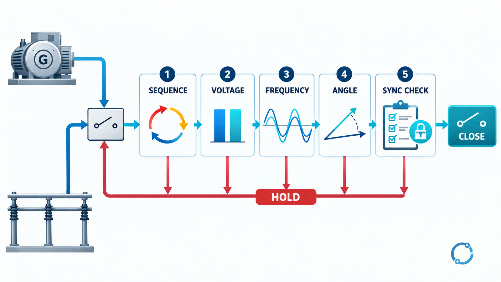
Before a generator is paralleled, the authorized operator must establish more than a single satisfactory meter reading. Confirm the generator and bus identity, verify phase sequence and the relationship between voltage, frequency and phase angle, then confirm the sync-check and close-permission path. Close only through the approved procedure. If the indication, equipment identity, control state or authority is unclear, stop and escalate.
That is the controlling answer. This page explains a pre-close verification sequence, not a universal synchronizing window. The acceptable thresholds, breaker timing, synchroscope behavior and permissive logic belong to the specific generator, switchgear, relay settings and approved operating procedure.
Generator paralleling is consequential energized work. It should be performed only by qualified, authorized personnel under the employer’s switching procedure, risk assessment and competency framework. OSHA 29 CFR 1910.333 provides relevant U.S. general-industry safety context, but local law, the site’s approved procedure and applicable standards remain governing. This article does not authorize bypassing a sync-check, interlock, permit or control-system restriction.
Define the task and the close boundary
The task is to verify readiness for one defined switching action: closing a named paralleling device between a named generator source and a named bus. It is not a general instruction to start a generator, test a protection relay, repair a control circuit or operate an unfamiliar synchronizing scheme.
Record before touching controls:
- the switching instruction or work permit that authorizes the activity;
- the generator identity, rating and current operating state;
- the bus identity, voltage level and source configuration into which it will be paralleled;
- the exact breaker, contactor or switch that will form the parallel connection;
- the approved operating procedure and revision;
- the sync-check, voltage-check and other permissive functions specified for this scheme;
- the authority who may grant the close, and the communication method;
- the contingency or abort path if conditions change during the check.
Two similar generators, adjacent bus sections or a transferred control point can turn a familiar-looking operation into the wrong action. Identity is part of the synchronization task, not clerical paperwork.
Establish the approved system state
Synchronization concerns the state immediately before closing. It does not justify taking a generator or bus into an unapproved condition.
The responsible operator should be able to state:
- which source will set the voltage and frequency;
- whether the generator is at a permitted speed and voltage;
- whether excitation, governor and control modes are in the approved state;
- whether the bus is live, dead or supplied from another source;
- what protections and interlocks are required in service;
- whether any alarms, trips, lockouts or abnormal indications are present;
- who has control of the breaker and whether remote or local control is selected;
- how loss of communications or a control-mode change will be handled.
Do not infer readiness from the fact that a control screen has presented a green indication. An indicator is a signal inside a scheme; it is not a replacement for confirming the identity, configuration and permission required by the approved procedure.
Check phase sequence before comparing magnitude
Phase sequence is a prerequisite. If conductors or instrument transformers are connected in an unexpected rotation, voltage and frequency readings can appear plausible while the phase relationship at the paralleling device is not. Rotating machinery can be damaged, protection can respond abnormally, or the closing action can create a serious electrical event.
Use the method required by the site and equipment documentation. Record:
- generator-side phase sequence;
- bus-side phase sequence;
- instrument-transformer polarity and wiring assumptions where the procedure requires them;
- the evidence that the measurement points correspond to the named phases;
- the result of any approved rotation or polarity check.
Do not invent a phase rotation by interpreting unrelated meter colors, wiring labels or screen symbols. Do not move control wiring to make a display agree unless that change is part of an authorized work activity and has been verified independently.
IEC 60034-1:2026 covers rating and performance for rotating electrical machines. It provides machine-level context for terminal quantities and operating performance; it does not supply a universal generator-synchronizing acceptance value. The approved scheme and equipment documentation define those acceptance criteria.
Compare voltage magnitude on both sides
After confirming identity and phase sequence, compare the voltage magnitudes that the approved synchronizing equipment is designed to measure. The check should align with the actual points on either side of the closing device.
- Use calibrated, approved indications.
- Confirm the selected voltage scales and ratios where relevant.
- Compare like with like: phase-to-phase or phase-to-neutral as specified by the procedure.
- Observe stability of the readings, not only a sampled display value.
- Compare the readings with the expected generator and bus operating state.
- Record both values and the approved criterion.
An approximate visible agreement is not enough to close if the required instrumentation, synchroscope or automatic synchronizer is not functioning as specified. Conversely, two equal voltage readings are not a complete synchronization check.
Do not use this article to set a voltage-difference limit. The generator capability, transformer/tap configuration, breaker permissives, relay settings and approved procedure determine the relevant condition.
Compare frequency and phase relationship together
Frequency indicates how the two source voltage phasors are moving relative to each other. Phase angle indicates where they are at the instant relevant to closing. They are not interchangeable.
- Observe both frequencies when the scheme requires a comparison.
- Verify that the reading source and measurement direction are correct.
- Understand the approved indication for relative phase movement.
- Account for the permitted closing time of the paralleling device as required by the approved scheme.
- Confirm that the intended close command will occur while the permitted phase-angle condition is present.
The last point is crucial. A displayed angle can be attractive one moment and no longer within the permitted condition when the breaker actually closes. The equipment’s timing and the approved synchronizing method determine how that is managed. This page does not provide a slip, angle, frequency-difference or timing value.
Some paralleling schemes use an automatic synchronizer, some use a controlled manual procedure with a synchroscope, and some use other permissive logic. Each requires its own approved check. Do not transplant a technique from a different plant or assume that an automatic function removes the operator’s responsibility to establish the state and authority.
Treat measurement as evidence, permission as a separate gate
The most important distinction in generator paralleling is:
| Question | Evidence | Release condition |
|---|---|---|
| Are the generator and bus correctly identified? | Tag, diagram, approved point and control state | Identity confirmed without ambiguity |
| Are phase sequence and phase relationships correct? | Approved measurement or check | Meets the scheme’s required condition |
| Are voltage and frequency in the approved relationship? | Approved instruments and values | Meets the applicable procedure |
| Is the phase angle appropriate for the commanded close? | Approved synchronizing check or synchronizer | Meets the applicable scheme criteria |
| Does the control system permit closing? | Sync-check, permissives, interlocks and alarms | All required permissions present |
| Has the authorized operator received approval to close? | Switching instruction and communication record | Authority and sequence confirmed |
No row substitutes for another. A healthy sync-check relay does not make a wrong generator identity correct. An equal voltage reading does not prove a functioning close permissive. A close permit does not authorize a person to ignore the approved procedure.
Confirm the sync-check and close-permission path
Before the close, make the approved checks explicit:
- confirm the required sync-check function is in service, not blocked or overridden;
- confirm voltage and phase-angle inputs exist at the synchronizing device where the procedure requires it;
- inspect any permissive or interlock status in the approved HMI or control interface;
- confirm that the selected breaker is the one governed by the synchronizing function;
- confirm the control mode and command destination;
- verify that alarms, trip conditions and lockouts that should prevent closing have cleared through the proper process;
- have the authorized person state the approved close criterion and the planned command;
- communicate the countdown or confirmation required by the switching procedure.
If a protective function operates, a sync-check permissive is blocked, a control selector changes, a voltage signal disappears or a measured value becomes unstable, do not force the operation. Hold the step, preserve the indication and follow the site’s abnormal-condition procedure.
Do not reset a lockout, defeat a permissive or change relay logic as part of synchronizing. Those actions require a separately authorized protection or maintenance procedure. The lockout relay trip and reset article provides the conceptual protection boundary, while the station procedure controls the actual operation.
Command the close through the approved path
Once the required verification and permissions are complete, operate the specified paralleling device by the approved local or remote control path. Do not use an unapproved bypass, test switch position, direct breaker mechanism operation or emergency override to complete a normal synchronizing step.
During and immediately after the commanded close:
- observe whether the expected state indication appears;
- confirm the generator and bus are connected as intended;
- monitor the generator loading and assigned control response;
- watch for alarms, oscillations, abnormal current or unexpected protection operation;
- confirm that the paralleling device and control system remain in the intended mode;
- report and record the result.
The specific post-close readings and load-transfer sequence belong to the site’s operating procedure. This article does not define them because generator capability, prime-mover response, excitation control, network conditions and operator roles vary.
Stop on ambiguity
Stop and escalate rather than proceeding when:
- generator, bus or breaker identity cannot be confirmed;
- the approved procedure or current revision is unavailable;
- the person giving the close has no verified authority;
- phase sequence, polarity or measurement-source integrity is uncertain;
- approved voltage, frequency, phase-angle or sync-check indications disagree;
- the synchronizer, relay, instrument transformer circuit or control path has an unexplained alarm;
- a permissive, interlock, trip or lockout is blocked or unexplained;
- the control mode changes unexpectedly;
- the switchgear or generator shows abnormal sound, vibration, temperature or electrical behavior before the close;
- communications fail during a coordinated step;
- any required post-close indication does not behave as expected.
Escalation is not a technique failure. It is the correct control response when the evidence needed for a safe close is incomplete.
Record the synchronization
A useful record lets another authorized person reconstruct what was checked:
- date and time;
- generator, bus and paralleling-device identifiers;
- switching instruction or permit;
- procedure revision;
- identity and role of the operator and authorizer;
- measurement points and approved instruments;
- phase-sequence result;
- voltage and frequency evidence;
- phase-angle or synchronizing indication and applicable criterion reference;
- sync-check and permissive status;
- commanded close, equipment response and any exception;
- result, next operating state and handover notes.
Do not record claimed numerical readings unless they were actually observed through the approved instrumentation. If the procedure relies on an automatic synchronizer and does not require manual numerical values, record the functional evidence and status that the approved procedure requires.
Maintenance and test considerations belong to a separate boundary
Synchronizing inputs can be affected by:
- incorrect CT or VT wiring;
- a blown voltage fuse or disconnected signal;
- a test block left in an abnormal position;
- relay setting changes;
- breaker timing changes;
- incorrect control-cable selection;
- software or HMI configuration changes;
- loss of time synchronisation or event recording;
- a defective synchronizer or annunciator.
Those conditions call for an approved protection and control test, not an improvised field adjustment during a close. Maintenance evidence should be retained separately and linked to the equipment and settings it tested.
The closed-transition transfer-switch coordination guide covers a different arrangement and sequence boundary; it should not be treated as a substitute for the generator synchronizing procedure. Similarly, generator-circuit-breaker breaking capacity addresses fault interruption, not the pre-close synchronization decision.
Completion test
You have completed the verification task only when:
- the generator, bus and paralleling device are unambiguously identified;
- the approved operating state and authority are established;
- phase sequence and the required measurement sources are verified;
- the approved voltage, frequency and phase-angle criteria are satisfied;
- the sync-check and all required permissions are confirmed;
- the approved person has commanded the close through the permitted path;
- the expected connection and post-close response have been observed;
- the result, or the stop condition, is recorded.
If any item is incomplete, do not treat the operation as successfully completed.
Practical conclusion
Generator paralleling is a permission-first activity. The technical evidence matters: phase sequence, voltage, frequency and phase angle must all be correct. So does the control evidence: the right generator and bus, a functioning sync-check, the required interlocks and an authorized close command. The strongest habit is to keep those questions separate, stop when one cannot be answered, and leave the actual acceptance thresholds to the approved machine, breaker, relay and operating procedure.
Sources
- IEC 60034-1:2026: Rotating electrical machines, Part 1: Rating and performance, published 2026, edition 15.0.
- OSHA 29 CFR 1910.333: Selection and use of work practices, U.S. general-industry electrical safety context; local law and approved site procedures remain governing.