
Capacitance cannot be converted to kilovolt-amperes reactive (kVAR) on its own. You also need the RMS voltage actually across each capacitor, the supply frequency, and—for three-phase banks—the connection and whether the capacitance is per branch. For an ideal single capacitor on a sinusoidal supply:
kVAR = 2π × frequency (Hz) × capacitance (µF) × voltage² (V²) × 10⁻⁹.
The reverse is µF = kVAR ÷ [2π × frequency × voltage² × 10⁻⁹]. These are reactive-power magnitudes; using the common passive sign convention, the capacitor’s reactive power is negative. Neither expression is a complete equipment-selection calculation.
Identify the voltage before choosing a formula
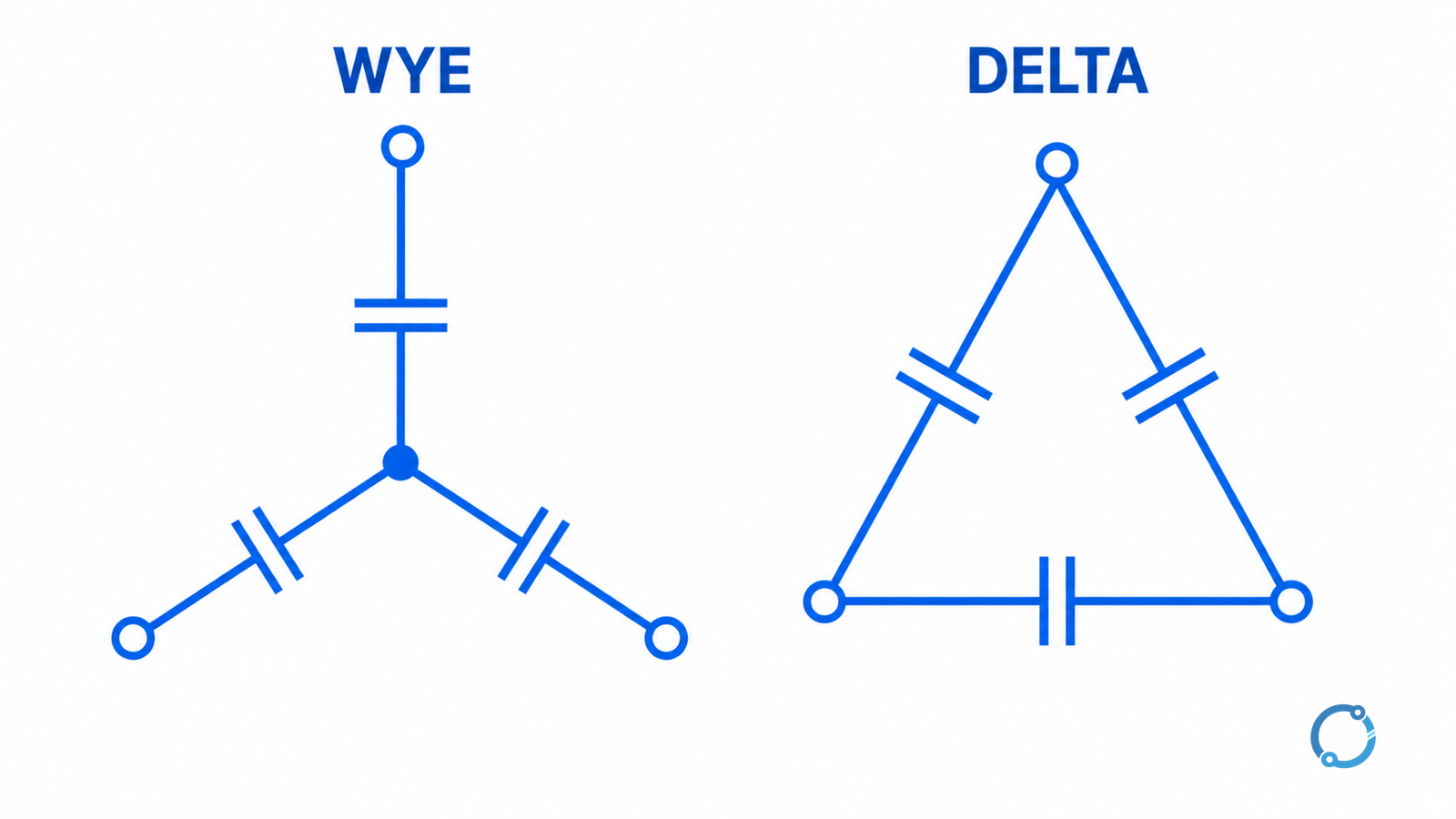
The voltage in the single-capacitor equation is the RMS voltage across that capacitor, not automatically the system’s line-to-line voltage. In a balanced three-phase bank, the relationship depends on connection. The table assumes three identical branches, equal sinusoidal voltages and capacitance C per branch. VL is the three-phase line-to-line RMS voltage.
| Arrangement | Voltage across each branch | Total ideal bank kVAR |
|---|---|---|
| One capacitor | V | 2πf × CµF × V² × 10⁻⁹ |
| Three-phase wye | VL/√3 | 2πf × CµF × VL² × 10⁻⁹ |
| Three-phase delta | VL | 3 × 2πf × CµF × VL² × 10⁻⁹ |
The wye expression contains three branches too: each is exposed to VL/√3, so the factors of three cancel when voltage is squared. The delta expression includes three branches each exposed to VL. With the same line voltage, frequency and capacitance per branch, ideal delta reactive power is three times the wye value. That statement does not mean the two assemblies are interchangeable or that their individual components have the same voltage rating.
One equivalent capacitance is not always three branch values
A nameplate or test record may give capacitance per element, per phase, between terminals, or as a bank equivalent. Those are different measurement bases. A measured value between two terminals can include the other branches and is not automatically a branch’s value. Confirm the test connection and the manufacturer’s method before inserting a value in the table. Similarly, if a specification gives total installed capacitance, do not silently treat it as the capacitance of each of three equal branches.
For a single-phase capacitor connected line-to-line, use that actual line-to-line voltage as V in the single-phase row. For a capacitor connected line-to-neutral, use the actual line-to-neutral voltage. A nominal voltage by itself is not proof of the voltage at the terminals under the condition being studied.
Worked example: µF to kVAR
Assume an ideal balanced three-phase bank on a 400 V line-to-line, 50 Hz sinusoidal supply. Each of its three branches is 100 µF. The numbers below are an illustrative calculation, not equipment ratings.
For wye, the total is:
Q = 2π × 50 × 100 × 400² × 10⁻⁹ = 5.03 kVAR.
The cross-check is to calculate each branch at 400/√3 ≈ 230.94 V: each supplies about 1.68 kVAR, for about 5.03 kVAR in total. Round only after calculating if accuracy matters.
For delta, each branch sees 400 V, so:
Q = 3 × 2π × 50 × 100 × 400² × 10⁻⁹ = 15.08 kVAR.
The branch voltage rating, switching duty and protection required for the two configurations are different engineering questions. The example does not authorize reconnecting a bank from one arrangement to another.
Worked example: kVAR to µF
Suppose the requested ideal output is 10 kVAR at 400 V line-to-line and 50 Hz, from a balanced delta bank with three equal branches. Rearrange the delta equation:
CµF per branch = 10 ÷ [3 × 2π × 50 × 400² × 10⁻⁹] = 66.31 µF.
This is approximately 66.3 µF per branch, not 66.3 µF for the complete bank. A reverse calculation using the delta row returns 10 kVAR apart from rounding. The theoretical total of three branch capacitance numbers is about 198.9 µF, but that sum is not a license to use the single-phase equation at line voltage without the correct topology.
For the same 10 kVAR and line voltage in wye, the result is about 198.9 µF per branch, because each branch has a lower voltage. Practical equipment would still need ratings and verification appropriate to its real operating duty.
Why voltage and frequency change the result
For a fixed ideal capacitance, reactive-power magnitude is proportional to frequency and to the square of the actual RMS voltage. If frequency rises from 50 to 60 Hz with the same voltage, the ideal result increases by 20%. If voltage increases by 10%, the ideal result becomes 1.1², or 1.21 times the original value. These are mathematical comparisons at the stated conditions, not permission to operate a capacitor above its rating.
The physical basis is capacitive reactance, Xc = 1/(2πfC), with C in farads. The U.S. Department of Energy’s electrical-science fundamentals handbook describes the relationship between capacitance, frequency and AC current. Combining I = V/Xc with reactive power magnitude Q = VI gives Q = 2πfCV² for a single ideal capacitor. Converting farads to microfarads and var to kVAR produces the 10⁻⁹ factor.
A quick check before using the result
- Record frequency and the voltage at the capacitor, with units and whether it is line-to-line or branch voltage.
- Identify single-phase, wye or delta, and verify if the capacitance is per branch, per element or a measured equivalent.
- Select the corresponding equation and keep µF, V and Hz consistent. Use kVAR as the magnitude unless the calculation explicitly tracks reactive-power sign.
- Reverse the calculation to check arithmetic. A factor-of-three discrepancy often signals confusion between wye and delta or between branch and total quantities.
- Label the output as theoretical, at the stated voltage and frequency. Do not treat it as a confirmed nameplate rating or an acceptance test.
For a bank of unequal branches, a balanced three-phase shortcut is inappropriate. Evaluate the actual branch voltages and capacitances using an appropriate network model. Harmonic voltage components also need separate consideration: the fundamental-frequency result alone does not represent the full capacitor current and losses in a distorted system. Detuned banks with series reactors require the complete branch impedance rather than the bare-capacitor shortcut.
Conversion is not capacitor-bank selection
The result describes an ideal reactive-power relationship; it does not decide the required compensation, discharge arrangements, circuit switching, harmonics, resonance, overvoltage, available fault current, thermal duty or protection. Bank rating and acceptable operating limits must come from the actual equipment documentation and the applicable design standard. For example, the IEC 60871-1 catalog entry has a specific scope for shunt capacitors above 1 kV AC; it should not be presented as a universal approval of every installation.
To understand the wider decision, see why power factor may need correction and how a capacitor-bank panel controls its steps. A numeric conversion does not establish whether additional compensation is appropriate for a particular system.
Capacitors can retain hazardous energy after disconnection. Planning and measurements belong to qualified personnel using site procedures, identified sources, appropriate isolation, stored-energy controls and verified absence of voltage. In U.S. general industry, consult the applicable OSHA electrical safe-work rules. The applicable local rules and manufacturer instructions govern elsewhere.