

“Can a breaker or switch be installed in the neutral?” has no useful worldwide yes-or-no answer. A separate neutral pole operating with the line poles is different from a device that interrupts only the neutral. Neutral-current sensing is different again. The first task is to identify conductor function, device action and jurisdiction—not simply count the poles.
This guide separates UK safety guidance from U.S. workplace overcurrent requirements. It does not provide field wiring instructions or permission to modify a protective or combined protective-and-neutral conductor. Qualified designers must check the adopted installation rules, device documentation and all supply sources for the actual system.
Name the conductor and the intended action
| Function | What must be distinguished | Design evidence to request |
|---|---|---|
| Separate neutral, N | Normal load-return conductor versus an independent opening point | Whether and when N opens relative to all associated line poles |
| Protective conductor, PE | Protective continuity, not normal load control | Uninterrupted protective path in the proposed switching arrangement |
| Combined protective-and-neutral, PEN | Both functions in one conductor | System boundary and continuity protection; do not treat it as an ordinary N pole |
| Neutral-current sensor | Measurement versus an interrupting contact | Which protective action follows detection and which conductors open |
Labels such as “1P+N,” “2P” or “4P” do not, on their own, establish which poles contain overcurrent sensing, how they operate or whether the device is suitable for isolation. Verify the exact functional diagram and rating evidence. Two separate single-pole devices are not proof of an approved linked-pole arrangement.
Why opening only the neutral can leave a hazard
If a load stops operating because its return path opens, its line-side connection may still be energized. A stopped appliance is therefore not evidence of isolation. In a shared three-phase neutral arrangement, loss of the neutral can also disturb the reference for phase-to-neutral loads; the result depends on the connected impedances and supply arrangement.
Neither consequence can be resolved by assuming “neutral means zero volts.” The installation must account for normal operation, abnormal states and work conditions. These mechanisms explain why the action of a neutral pole matters independently of whether current was flowing when a device operated.
The switch and socket safety guide treats symptoms and inspection boundaries. It is not a basis for installing a neutral-only disconnect as a remedy.
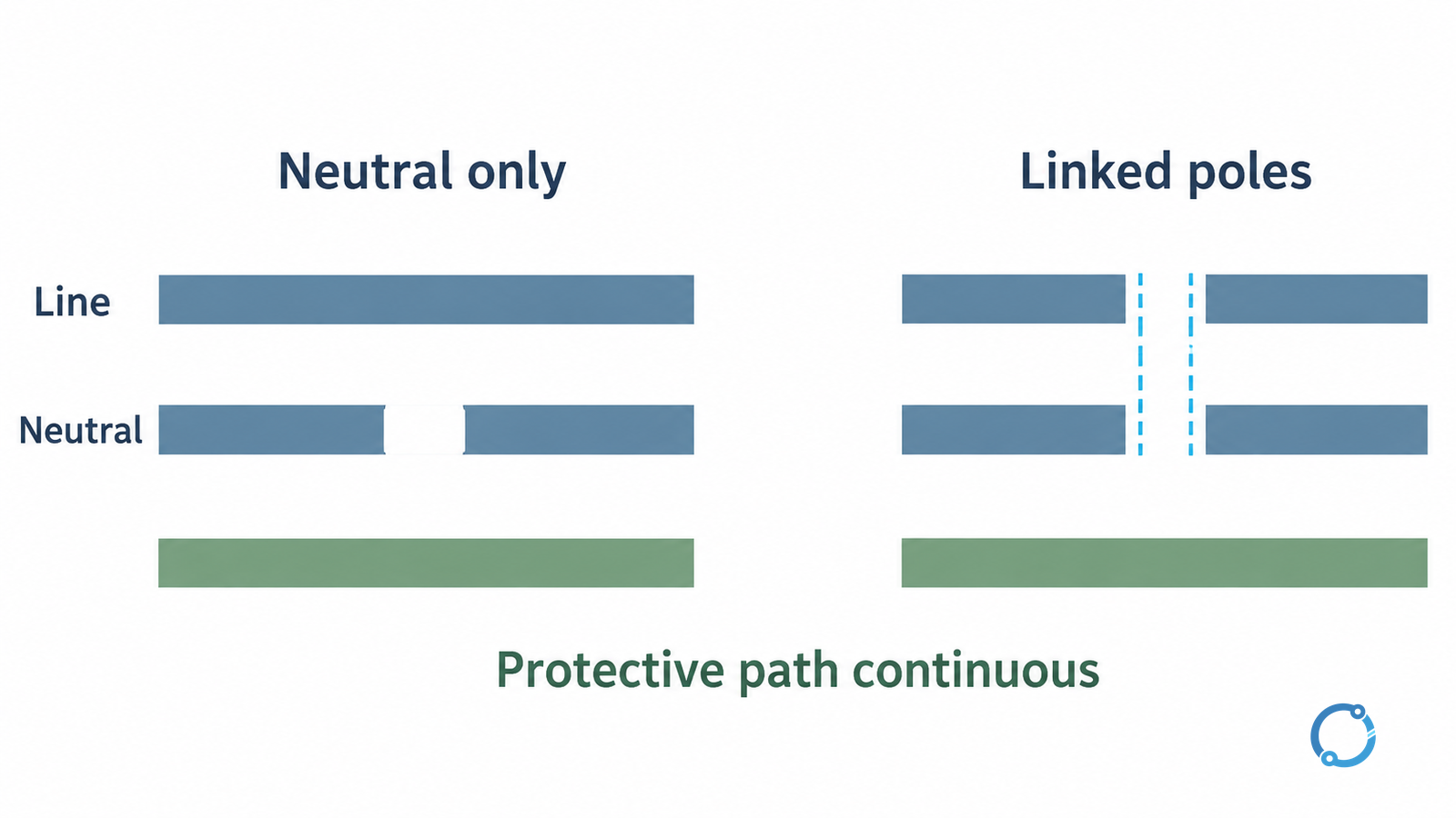
Keep the UK and U.S. statements in their own scopes
| Authority | Relevant scope | What it does not establish |
|---|---|---|
| UK HSE, HSR25, 2015, paragraphs 155–158 | Integrity of referenced conductors and precautions concerning neutral devices | A worldwide device selection rule or a current BS 7671 clause lookup |
| U.S. OSHA, 1910.304(f)(1)(ii) | Grounded-conductor overcurrent interruption within the section’s 600 V-or-less scope | A general rule for every functional or isolation switch |
| IET, 2023 isolation article | Discussion based on BS 7671:2018+A2:2022 | Proof that every cited edition detail is the adopted rule for a 2026 project |
In HSE HSR25, paragraph 155 emphasizes the danger of losing combined neutral/protective continuity. Paragraph 157 addresses neutral-fuse risks in fixed power distribution, while noting a bounded exception inside self-contained plug-connected equipment. Paragraph 158 recommends, in general, switching N with all related phases, N opening last and closing first, without interrupting PE. These distinctions do not authorize a field alteration to PEN.
OSHA 1910.304(f)(1)(ii) addresses overcurrent devices interrupting a grounded conductor. Within its stated scope, and except for motor-running overload protection, such interruption requires simultaneous opening of all circuit conductors. Read this as an overcurrent requirement with its scope and exception—not as a universal answer about neutral isolation.
The IET’s 2023 isolation discussion also shows why earthing arrangement and the reliability of the neutral reference affect isolation decisions. Check the adopted edition and actual system rather than copying a dated exception into a new specification.
Separate sensing, disconnection and isolation capability
A device may measure neutral current and trip associated line poles without putting an independently operating protective element in the neutral. Conversely, a switched neutral pole may have no neutral overcurrent sensing. State both functions in the design record.
Residual-current protection is another distinct function. Passing a neutral through a residual-current sensing arrangement does not make that neutral a protective conductor, and it does not prove the device supplies every required isolation function. The GFCI and AFCI guide explains the different hazard objectives; use model-specific evidence for the actual pole action.
If isolation is required, verify the device’s declared isolation suitability, operation of associated conductors, supply-source boundary and means of securing the state. An open-position indication alone does not demonstrate absence of hazardous voltage at the work location.
Close the conductor-action record before release
For each proposed device, record the circuit and supply sources, earthing arrangement, N/PE/PEN functions, sensing elements, opening action, required contact sequence and applicable rule. Identify any assumption about backfeed or another supply and resolve it through the approved system design.
The HSE safe-working guidance requires a safe approach to disconnection, preventing inadvertent re-energization and checking that equipment is dead. Personnel must follow the applicable isolation procedure; this article is not an instruction to open a loaded neutral for testing. The modular switch/socket installation checklist supplies adjacent verification context, not authority to change conductor functions.
The decision is complete when the action of every conductor is documented and acceptable under the project’s own rules. “The neutral was switched” is too little information; “these verified poles provide this required action while preserving protective continuity” is a reviewable engineering statement.