
A low-voltage protective device is not specified by its ampere rating alone. The current must match the load and installation basis; the breaking capacity must match the prospective fault current at the device’s voltage; the trip or residual-current characteristic must match the protection job; and the voltage, poles, frequency and standard route must all describe the same product. One attractive number cannot fill the other four fields.
The practical sequence is to build a compatibility record before comparing products. Record the circuit voltage and earthing arrangement, expected load and duty, calculated fault level, required protection functions, and the standard or product family that defines each claimed rating. Then ask for evidence that connects those fields to the exact device and application.
This guide covers low-voltage protective devices used in electrical panels and similar assemblies. It does not replace a fault study, a selectivity study, the locally adopted electrical code, or a product’s installation instructions. It also does not turn a standard’s scope into a claim that a particular product is certified.
Match five fields before reading a catalogue
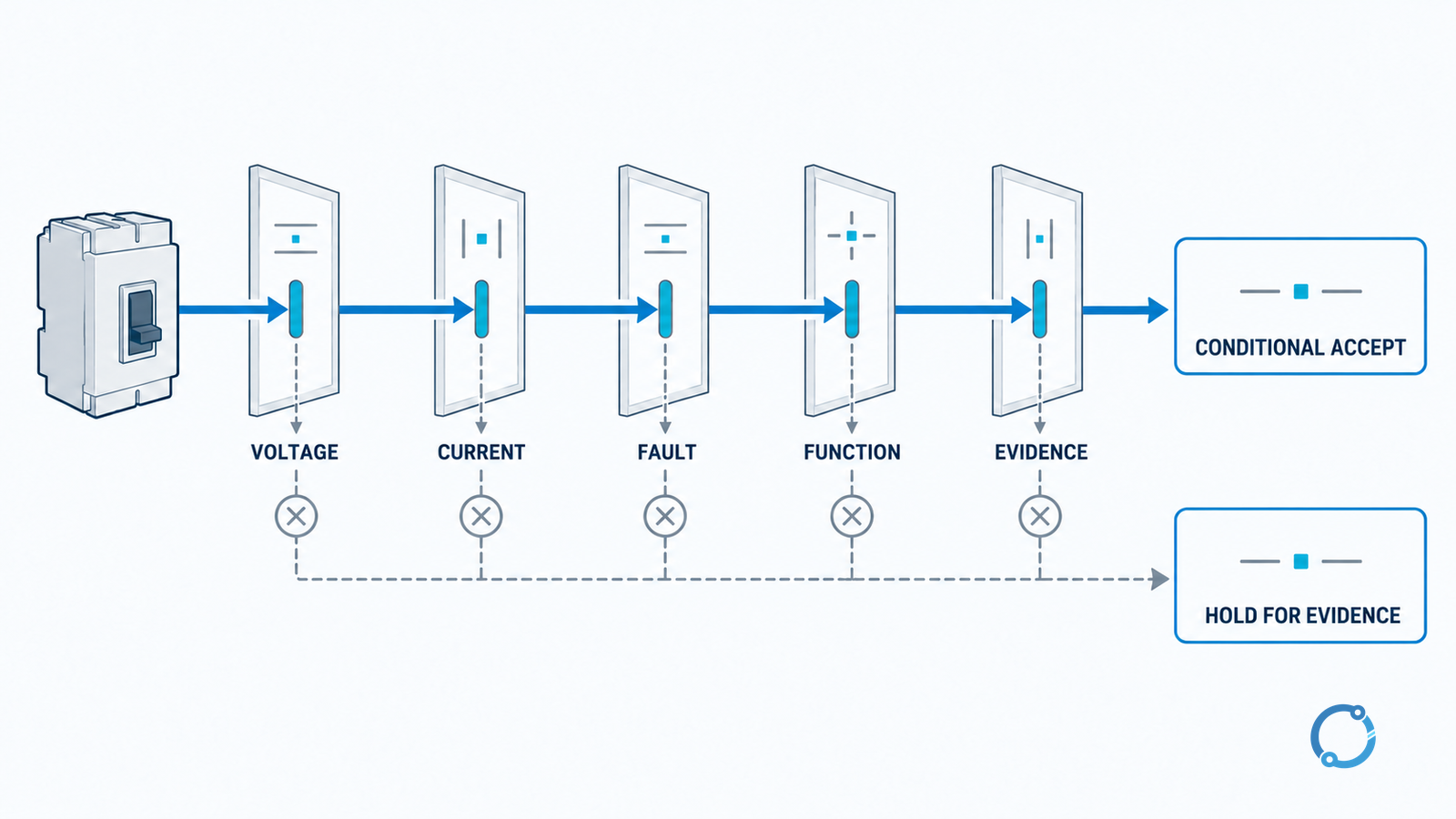
Use a five-field gate. The order is deliberate because a later comparison cannot repair an earlier mismatch.
| Field | What must match the circuit | Evidence to obtain | Stop condition |
|---|---|---|---|
| Voltage and system basis | Rated voltage, AC or DC, frequency, poles, and voltage-to-ground assumptions | Product marking and applicable product-family record | The device’s voltage or pole basis is not stated |
| Current and thermal basis | Load current, duty cycle, ambient, enclosure, mounting, conductor size, and termination | Load calculation plus the exact product’s current and derating basis | One value uses a different ambient or installation assumption |
| Breaking capacity | Prospective fault current at the device location and the voltage at which the rating is claimed | Fault study and a verified rating with the same voltage and test basis | A bare kA figure is being compared across unlike conditions |
| Protection function | Overload, short-circuit, residual-current, isolation, or a defined combination | Published trip or residual-current characteristic and the intended function | A device is being used for a function it does not provide |
| Compatibility and evidence | Series rating, neutral, accessories, frequency, terminals, and assembly listing | Approved combination or equipment documentation | The combination is assumed rather than documented |
The table is not a scorecard. A field that remains unknown is a hold point. For a panel specification, it is better to leave a candidate unapproved than to fill a missing basis with a convenient assumption.
Start with voltage, poles and the earthing basis
The voltage rating of a protective device is not a single universal number. AC and DC have different interruption behavior, and the allowable voltage may depend on how poles are connected and how the system is earthed. A device marked for one arrangement cannot be moved to another merely because the nominal system voltage looks similar.
Use the circuit diagram to record:
- nominal system voltage and frequency or DC;
- number of poles and whether the neutral is switched or protected;
- phase-to-phase and phase-to-ground conditions relevant to the product;
- whether the device is intended to isolate or disconnect the circuit;
- the product-family standard that defines the claimed voltage and pole arrangement.
IEC 60947-2:2024 applies to circuit-breakers intended to be installed and operated by instructed or skilled persons, with main contacts for circuits not exceeding 1,000 V AC or 1,500 V DC. That is a scope statement for the standard, not a statement that every breaker within those limits is suitable for a particular panel. The exact product marking and application evidence still decide.
The same discipline applies to miniature circuit breakers. IEC 60898-1:2015+AMD1:2019 applies to AC air-break circuit-breakers for household and similar installations, with a rated voltage not exceeding 440 V between phases, a rated current not exceeding 125 A, and a rated short-circuit capacity not exceeding 25,000 A. These are scope limits. A product outside the scope is not therefore bad; it may belong to another standard family.
Current rating is a thermal statement, not just a load number
Rated current is the current the device can carry under the conditions defined by its standard and the manufacturer’s data. The load calculation, ambient temperature, enclosure, mounting orientation, grouping, conductor termination, and duty cycle can all change the usable value. The right question is not “Does the load current sit below the number?” but “Does the load current sit below the verified current for this installed arrangement?”
The circuit-breaker sizing workflow shows why a load-only chart is incomplete. Use it to establish the required current basis, then move to the protective device’s own data. The OHELE discussion of MCCB fundamentals is useful when the device is a molded-case breaker rather than a miniature breaker, because the trip unit and frame current introduce separate fields.
Keep these current values separate in the record:
- calculated load current;
- design current after diversity or duty assumptions;
- continuous current allowed by the selected conductor and termination;
- protective-device rated current and its installation basis;
- any setting or adjustment that changes the actual protection threshold.
If the device has an adjustable trip unit, record the setting and the evidence for it. Do not write the frame rating in the “protected current” column and assume the setting follows.
Breaking capacity needs a voltage and a fault location
Breaking capacity, often shown in kiloamperes, is the fault current the device is rated to interrupt under stated conditions. A kA value without a voltage, pole configuration, test basis, and prospective fault location is not a complete selection input. The same number can be acceptable at one voltage and not at another; it can also be valid for one connection arrangement and irrelevant to another.
The U.S. OSHA electrical installation rule for general equipment states that equipment intended to interrupt current at fault levels must have an interrupting rating sufficient for the nominal circuit voltage and the current available at the line terminals. That is a useful cross-check even outside the United States: the fault current and voltage at the device location are the starting point, not the service size or a generic panel label.
Use the fault study to record:
- prospective symmetrical and peak values as applicable to the study;
- fault location at the line terminals of the protective device;
- system voltage and the device’s rated voltage;
- whether the fault contribution includes motors, generators, or another source;
- the breaking duty and test basis attached to the product rating;
- any series-rated or combination arrangement, supported by the equipment documentation.
Do not compare a device’s isolated kA number with a system’s available fault current until both have the same voltage and basis. If the equipment uses a series combination, the approved combination is part of the evidence. A higher standalone rating cannot be substituted for a tested or listed combination merely because the arithmetic appears safer.
Trip basis and the protection function must be explicit
A breaker’s current rating does not fully describe its response. The trip curve or trip-unit setting determines how the device responds to overload and short-circuit current, and the intended protection function decides which response is required. A device selected for branch-circuit overcurrent protection is not interchangeable with a supplementary protector that is intended for use inside equipment.
UL’s public circuit-breaker guidance draws that U.S. distinction directly: a circuit breaker provides service-entrance, feeder, or branch-circuit protection under the NEC, while a supplementary protector is not intended to provide branch-circuit overcurrent protection required by the NEC. The UL evaluation routes also differ: UL 489 is used for molded-case circuit breakers, while UL 1077 is the supplementary-protector route. Those statements identify product categories; they do not certify a particular catalogue number.
For IEC equipment, check the product-family standard and the published characteristic. IEC 60947-2 covers circuit-breakers in its stated low-voltage scope. IEC 60898-1 covers a narrower household and similar-installation family. The two families may use familiar letters or numbers in different ways. Do not assume that a “B,” “C,” or “D” label has the same meaning across standards without reading the product data.
Where selective coordination is required, the trip basis becomes a system question rather than a single-device question. The OHELE guide to LV breaker selectivity explains the need to compare time-current behavior, fault current, and upstream/downstream evidence. A breaker that is individually adequate can still be a poor pair if the downstream device does not clear its fault before the upstream device trips.
RCCB, RCBO and MCB are not three names for one function
The abbreviations are often mixed in searches. Keep the functions separate.
An MCB is a miniature circuit breaker intended for overcurrent protection within its product scope. An RCCB is a residual current operated circuit-breaker without integral overcurrent protection. IEC 61008-1:2024 describes RCCBs for household and similar uses, with rated operational voltages not exceeding 440 V AC and rated currents not exceeding 125 A, principally for protection against shock hazard. An RCBO is a residual current operated circuit-breaker with integral overcurrent protection; IEC 61009-1:2024 is its general-rules standard.
That means an RCCB does not replace an overcurrent device simply because it has a current rating printed on it. The current marking is part of the device’s rating basis, not proof that it provides overload and short-circuit protection. An RCBO may combine functions, but its overcurrent characteristic, residual-current type, voltage, poles, and breaking capacity still need to be matched to the circuit.
Residual-current type is another compatibility field. The OHELE guide to AC, A, F and B residual-current types explains why the waveform and application determine the appropriate choice. Selecting an arbitrary residual-current type because it is available is not an evidence-based decision.
The standard route is not a compliance certificate
A product-family standard tells you what kind of document governs a device category and how its requirements are organized. It does not prove that a particular product passed every relevant test, that a particular factory follows the standard, or that the device is acceptable in the local installation. Those are separate questions of product evidence, certification or listing where applicable, and code adoption.
Build a status column in the compatibility record:
- Scope only: the device category falls within the cited standard’s public scope.
- Product data: the exact catalogue number states the ratings and characteristics being used.
- Test or certification evidence: a controlled report, certificate, listing record, or other accepted evidence supports the claim.
- Application evidence: the device, its accessories, its enclosure, and its combination with other equipment are acceptable for the intended installation.
Never collapse these into a single check mark. A device can have a valid product data sheet and still be wrong for the fault level. A panel can contain listed components and still fail a combination or assembly requirement. The appropriate authority, standard, and local code determine what evidence is needed.
For a fuse-versus-breaker choice, the comparison also has to stay on the same protection task. The OHELE article on MCBs versus fuses is a useful boundary check, but it does not remove the need to verify the exact device’s voltage and fault ratings.
A worked compatibility record
Consider a three-phase AC feeder in a low-voltage panel. The designer knows the load calculation, conductor size, and a prospective fault current from a study. A proposed device lists a 100 A frame, an adjustable trip unit, a 50 kA breaking capacity, and a 400 V rating. Do not approve it yet.
The record still needs:
| Question | Acceptable evidence | If missing |
|---|---|---|
| Does 400 V match the system and pole arrangement? | Product marking and voltage basis | Hold the candidate |
| Is 100 A the protected current or only the frame size? | Trip-unit setting and characteristic | Hold the candidate |
| Is the 50 kA value valid at the actual voltage and connection? | Exact product rating and fault-study comparison | Hold the candidate |
| Does the device provide the intended overcurrent function? | Published trip characteristic and application evidence | Choose another family or obtain evidence |
| Is any series combination or accessory arrangement approved? | Equipment documentation and combination record | Do not assume it |
| Is the assembly acceptable for the environment and installation? | Enclosure, ambient, termination, and assembly evidence | Refer to the panel designer |
Only after those fields are closed does the device become a shortlist candidate. The result is a specification record, not a sales recommendation.
A verification checklist
Before releasing the selection, confirm:
- The protective function is named: overload, short-circuit, residual current, isolation, or a defined combination.
- The circuit voltage, AC or DC, frequency, poles, and earthing basis are recorded.
- The load and conductor current bases are consistent with the device’s current basis.
- The prospective fault current and the device’s breaking capacity are compared at the same voltage and location.
- The trip curve or setting is stated and matches the intended protection and coordination.
- The standard route and the product evidence are recorded separately.
- Series ratings, neutral arrangements, accessories, and enclosure conditions are documented rather than assumed.
- The final selection is reviewed against the locally adopted code and the assembly’s requirements.
If any field is unresolved, the correct output is a hold point with the missing evidence named. That is more useful than a complete-looking table built on a number whose basis nobody can trace.
Sources
- IEC 60947-2:2024, circuit-breakers
- IEC 60898-1:2015+AMD1:2019, household and similar AC circuit-breakers
- IEC 61008-1:2024, RCCBs without integral overcurrent protection
- IEC 61009-1:2024, RCBOs with integral overcurrent protection
- UL circuit breaker and supplementary protector services
- 29 CFR 1910.303, electrical installation requirements
The IEC and UL pages were used for standard and product-category scope on 2026-10-23. The full standards are paywalled and were not accessed. The OSHA/eCFR citation is U.S.-specific and does not replace the locally adopted electrical code or a project specification. No product compliance, preferred trip threshold, or universal breaking-capacity value is implied.