
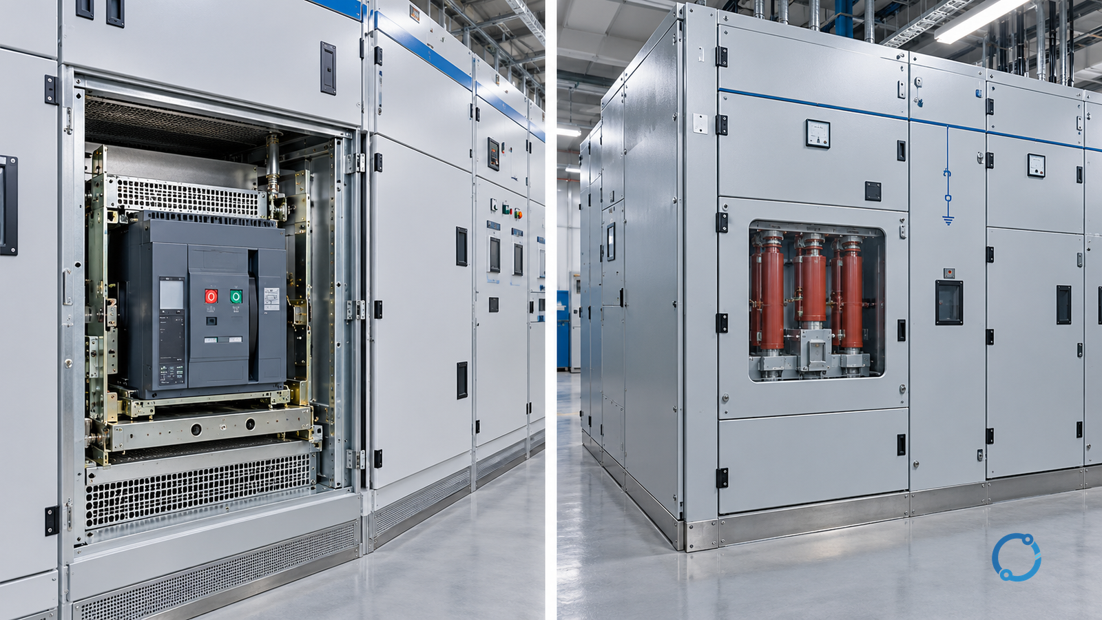
An air circuit breaker (ACB) and a vacuum circuit breaker (VCB) are not interchangeable options selected by current rating. In the conventional IEC equipment language used here, an ACB is a low-voltage switchgear circuit breaker within the scope of IEC 60947-2:2024, while a VCB is a high-voltage circuit breaker for systems above 1,000 V within the scope of IEC 62271-100:2021+AMD1:2024. The system voltage class, fault duty, switching application and assembly standard change before the interruption medium does.
That boundary is the first decision. A 1,250 A low-voltage main breaker and a 1,250 A high-voltage feeder breaker may share a number on a drawing, but they do not share the same insulation, fault level, switching environment, testing basis or protection responsibilities. Comparing them by current alone is a category error.
This article is a technical decision guide for the conventional ACB-versus-VCB question. It does not rank manufacturers, publish product ratings or claim that one technology wins across every application. It also does not supply universal maintenance intervals, switching-cycle figures or overvoltage limits. Use the exact product documentation, applicable assembly standard, project study and locally adopted requirements.
The short decision rule
Use an ACB when the application is a low-voltage circuit requiring a draw-out or fixed air-break switching device with the necessary current, short-circuit, selectivity and control features. Use a VCB when the application is a high-voltage circuit requiring a vacuum-interruption device with the specified insulation level, fault duty, switching duty and mechanical endurance.
If the proposed comparison crosses the 1,000 V AC boundary without a clear system reason, stop and verify the project definitions. Do not assume that a product called an “air circuit breaker” by a supplier has the same scope as the IEC low-voltage ACB in this article. Product-family names vary, and the nameplate, standard, voltage rating and intended switchgear assembly must be checked directly.
Fix the comparison basis before comparing technologies
Build a system record first:
| Input | Why it changes the decision |
|---|---|
| Rated and maximum system voltage | Determines the applicable product and insulation family |
| System earthing and neutral arrangement | Affects overvoltage, insulation coordination and protection |
| Prospective fault current and duration | Determines making, breaking and short-circuit withstand requirements |
| Continuous current and load profile | Determines thermal duty and device size basis |
| Switching frequency and operational role | Affects mechanical endurance, mechanism and maintenance planning |
| Motor, capacitor, transformer or generator load | Introduces switching-specific transient and recovery duties |
| Required breaking and making operations | Must match verified product capability |
| Protection and control requirements | Changes trip units, relays, sensors and communication |
| Ambient, altitude and enclosure | Alters insulation, cooling and derating assumptions |
| Space, access and operating concept | Determines fixed, draw-out or enclosed assembly design |
| Project standard and jurisdiction | Determines IEC, IEEE, local code and assembly requirements |
IEC 62271-1:2017+AMD1:2021 provides common specifications for high-voltage switchgear and controlgear in its scope. Its consolidated existence does not prove that a particular VCB, enclosure, relay or installation satisfies the project. The same caution applies to every product-standard citation in this article: standard scope, type testing, product compliance and project acceptance are separate evidence claims.
Voltage class and standards
IEC 60947-2 applies to circuit breakers whose main circuits are rated up to 1,000 V AC or 1,500 V DC, with a defined extension above 1,000 V AC in its scope. It is the relevant product-standard context for the conventional low-voltage ACB choice. IEC 62271-100 applies to three-phase AC circuit breakers above 1,000 V in its stated scope. The exact scope text, amendments and product declaration must be read with the standard.
The practical result is not simply “ACB is lower voltage, therefore weaker.” A low-voltage ACB may be the appropriate main device for a large low-voltage switchboard, with a high continuous current, sophisticated trip unit and draw-out arrangement. A VCB may be the appropriate device for a medium-voltage feeder where its vacuum interrupter and mechanism are designed for the relevant high-voltage insulation and fault conditions. Each is strong inside its intended domain.
Do not use the terms interchangeably with other devices:
- a miniature circuit breaker (MCB) is not a VCB;
- a molded-case circuit breaker (MCCB) is not automatically an ACB;
- an air-break disconnector is not necessarily a circuit breaker;
- a vacuum contactor is not a vacuum circuit breaker;
- an air-insulated switchgear assembly may contain a vacuum interrupter.
The assembly name describes insulation or construction; the circuit-breaker name describes a function and product family. Read the single-line diagram and product data together.
Fault current and short-circuit duty
Both device families must make, carry and break the fault currents assigned to them, but the duty is expressed within different product standards and system contexts. A low-voltage switchboard has one fault-level study and protection-coordination problem; a high-voltage substation or distribution system has another, including insulation coordination, system earthing and switching overvoltage considerations.
Do not compare a short-circuit current number without its:
- voltage basis;
- asymmetrical or peak requirement;
- short-circuit duration;
- making and breaking duty;
- upstream and downstream contributions;
- protection clearing time;
- device status and operating sequence.
An ACB’s current rating and breaking capacity are not proof that it can be used on a VCB system. A VCB’s high-voltage test evidence is not proof that it can be installed in a low-voltage assembly. The assembly, busbar, clearances, cable termination, relay scheme and protection study must all match the device family.
For low-voltage selection, OHELE’s low-voltage circuit-breaker selectivity and ANSI and IEC rating comparison guides explain how rating terminology differs between contexts. For high-voltage devices, verify the project’s fault duty and product declaration against the applicable IEC 62271 family rather than carrying a low-voltage breaker number into a medium-voltage design.
Interruption medium and switching environment
An air circuit breaker uses air as the interrupting and insulating medium in its defined construction. A vacuum circuit breaker interrupts current in a vacuum bottle and uses the surrounding switchgear insulation system for the external clearances and connections. The switchgear enclosure may be air-insulated or gas-insulated; those are separate system choices.
The difference should be evaluated through the whole switching environment:
| Dimension | ACB question | VCB question |
|---|---|---|
| Voltage and insulation | Low-voltage clearances and assembly construction | High-voltage phase spacing, bushings and insulation coordination |
| Interruption evidence | Low-voltage making and breaking ratings | High-voltage breaking, making and short-circuit tests |
| Operating mechanism | Spring, motor or stored-energy design stated by product | Mechanism type, energy source and operating sequence |
| Contact and arc management | Visible isolation, arc chutes and contact condition | Vacuum interrupter condition, travel and diagnostic evidence |
| Switching duty | Main, feeder, motor, generator or other specified duty | Feeder, transformer, motor, capacitor or other specified duty |
| Enclosure and access | Fixed or draw-out low-voltage assembly | Withdrawable, fixed or enclosed high-voltage arrangement |
| Protection interface | Trip unit, shunt trip, sensors and communications | Relays, CTs, VTs, trip coils and control logic |
The visible “open” state of an ACB can support a local isolation concept, while a vacuum interrupter may provide a visible gap only through the surrounding disconnector or withdrawable position. Do not infer safe isolation from the device family alone. Follow the approved switching procedure, isolation points and voltage-verification process.
Switching frequency and endurance
The mechanical and electrical life of a breaker depends on the exact product, current, voltage, operating sequence and maintenance status. There is no universal cycle count from the words “ACB” or “VCB.” A vacuum interrupter can be suitable for frequent high-voltage operations in a specified product design, but contact erosion, bellows, mechanism wear, trip energy and test intervals still matter. An ACB can be suitable for many low-voltage switching operations, but its contacts and arc-control parts also have a declared condition and maintenance basis.
Do not state that one family is maintenance-free. Obtain:
- rated mechanical and electrical endurance from the product data;
- required operating mechanism energy;
- contact-wear indicators and inspection method;
- interruption count and current-weighted duty where specified;
- trip and close coil requirements;
- manufacturer-specified maintenance and lubrication schedule;
- spare-parts and diagnostic strategy;
- evidence for the intended ambient and enclosure.
The choice may depend on duty, not just capital cost. A breaker expected to operate frequently, isolate during maintenance or perform automatic transfer duty should have its operation count and failure mode reviewed with the same care as the fault rating.
Vacuum-specific overvoltage and recovery-voltage checks
Vacuum interrupters can exhibit current chopping and other switching phenomena that interact with the motor, transformer, cable and system earthing. The existence of a VCB does not by itself mean the overvoltage is unacceptable, and an ACB does not automatically solve an overvoltage problem. The project must evaluate the load and the selected device together.
For an inductive load, review:
- the designer’s switching-overvoltage study or supplier guidance;
- the load insulation withstand;
- cable and busbar configuration;
- surge arresters or other protection;
- system earthing;
- the breaker’s declared switching capability;
- whether the operation is normal load breaking, motor starting, transformer energisation or fault clearing.
The OHELE article on current chopping in vacuum circuit breakers explains why this is an application dimension rather than a generic verdict. A comparison should ask for verified performance and a project-specific mitigation plan, not a generic claim that vacuum interruption is always better or worse.
Protection, control and selectivity
The interruption medium does not define the protection system. A low-voltage ACB often integrates a trip unit with adjustable protection and metering. A high-voltage VCB is normally part of a switchgear and relay scheme, with current and voltage transformers, protective relays, auxiliary supplies and interlocking.
Compare the complete control architecture:
| Question | ACB | VCB |
|---|---|---|
| Where is the protection logic? | Trip unit and/or upstream relay/control system | Protective relay and switchgear control system |
| How are measurements obtained? | Integral sensors or external CTs, depending on product | External or instrument-transformer based, depending on design |
| How is trip energy supplied? | Product-specific stored energy or control supply | Product-specific trip energy and station battery/UPS design |
| How is failure annunciated? | Trip unit diagnostics, communications and auxiliary contacts | Relay alarms, breaker auxiliary contacts and monitoring |
| How is maintenance isolation achieved? | Withdrawable or fixed isolation method | Withdrawable, disconnector or other approved isolation arrangement |
Selectivity and protection coordination must be studied for the actual topology. A VCB with a high breaking capacity can be badly coordinated with upstream protection, while an ACB with a capable trip unit can be misapplied if the fault levels, cable impedance or source configuration are not modelled. The device family is not a substitute for the study.
Environmental and installation considerations
The project surroundings affect both technologies but in different ways. A low-voltage ACB may be used with exposed busbars inside a metallic assembly where ventilation, dust, humidity and access are controlled. A high-voltage VCB may sit in a compartment with insulation, pressure, interlocking, earthing and clearances that are specific to the switchgear type.
Ask:
- what ambient and altitude assumptions apply?
- is the assembly indoor or outdoor?
- are there corrosive gases, salt, dust, moisture or condensation?
- how are ventilation and heat removal verified?
- what are the access and arc-flash boundaries?
- are there stored-energy, spring or hydraulic hazards?
- how is the switchgear compartment protected against internal arc or pressure effects where required?
- what is the seismic or vibration basis?
Do not choose a technology on environmental grounds without the assembly data. A VCB in a suitable high-voltage enclosure is not automatically better in a dirty, humid workshop than a correctly selected low-voltage ACB in its own enclosure.
Cases where the comparison is valid
The ACB-versus-VCB decision is valid when the system-level voltage class and application role genuinely lead to two candidate architectures. Examples include a new project where a high-voltage distribution scheme and a low-voltage distribution scheme are both being considered for a load, or a comparison of two breaker rooms serving different voltage levels. In those cases, compare the complete assembly, protection and operating consequences.
The comparison is invalid when:
- one option is proposed for a different system voltage;
- the continuous current is matched but the short-circuit or insulation duty is not;
- the device is selected without its switchgear assembly;
- the switching duty (motor, transformer, capacitor or generator) is not stated;
- maintenance intervals or costs are quoted without verified product and site data;
- one family is called “safer” without defining the hazard, standard and installation.
A fair comparison matrix
Use the same evidence quality for both sides:
| Criterion | Low-voltage ACB | High-voltage VCB | Required project evidence |
|---|---|---|---|
| Voltage scope | Low-voltage switchgear application | High-voltage application above 1,000 V | Single-line voltage and applicable standard |
| Continuous current | Device and assembly thermal data | Device and switchgear thermal data | Load schedule and ambient |
| Fault duty | Making, carrying and breaking evidence | High-voltage fault and insulation evidence | Fault study and equipment declaration |
| Switching duty | Main, feeder or specified load | Feeder, transformer, motor or specified load | Operation and system study |
| Endurance | Product mechanical/electrical data | Product mechanical/electrical data | Expected operations and maintenance plan |
| Overvoltage | Assembly and load interaction | Current chopping and recovery-voltage review | Load insulation and mitigation study |
| Protection | Trip unit/relay architecture | Relay, CT/VT and trip architecture | Coordination and control schedule |
| Isolation | Fixed/draw-out and visible-gap concept | Disconnector/withdrawable/earthing sequence | Approved switching procedure |
| Environment | Assembly ventilation and ingress | Compartment insulation and pressure/ventilation | Site and assembly data |
| Lifecycle | Verified spares and service plan | Verified spares and service plan | Owner maintenance strategy |
The matrix has no “winner” column because a complete system, not a product-name preference, determines the answer.
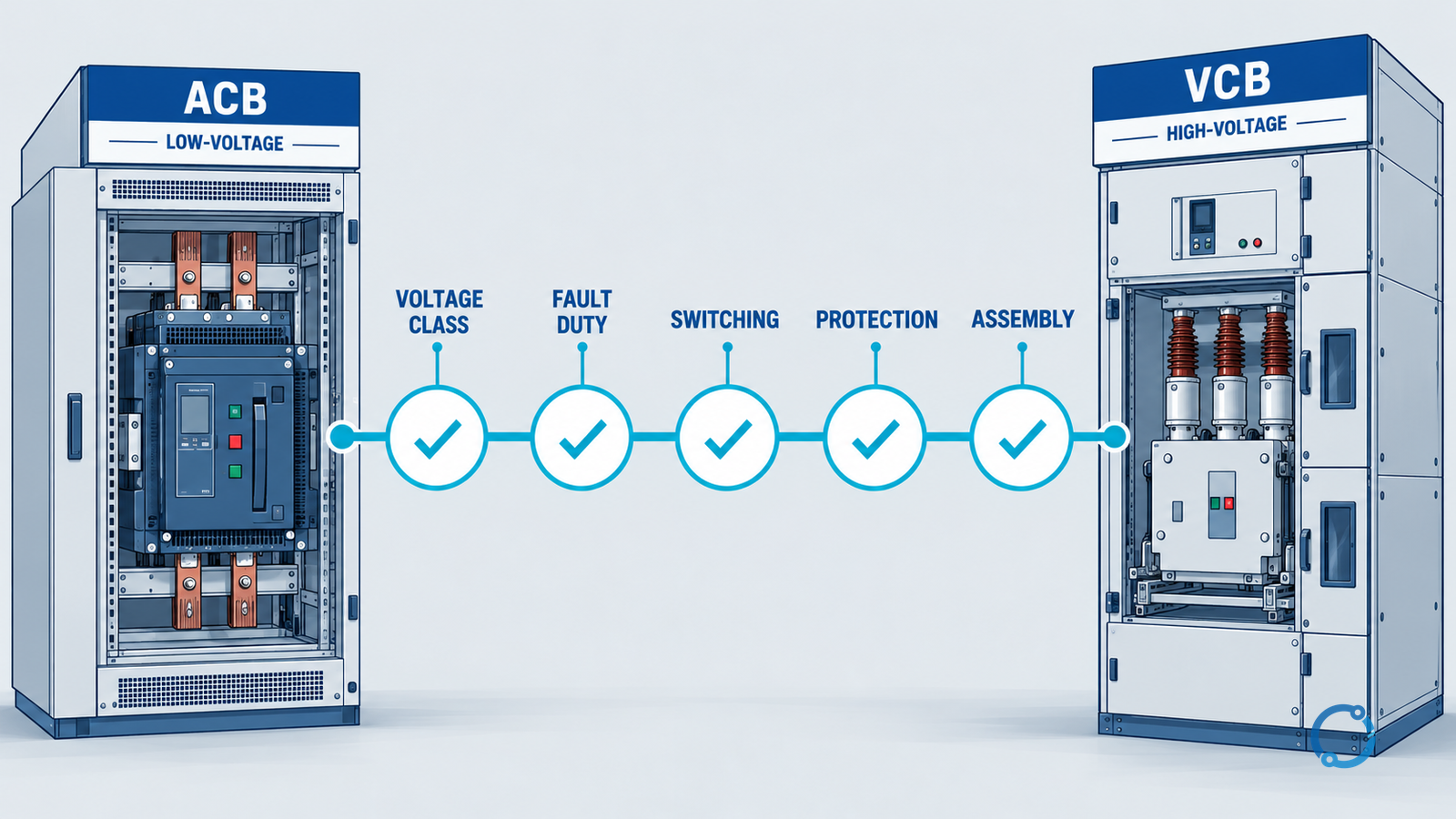
A practical selection sequence
Gate 1: confirm the system voltage and earthing
Select the product family only after defining the nominal, maximum and insulation coordination conditions. Record the system earthing arrangement, because it affects protection, overvoltage and the switchgear design.
Gate 2: establish continuous and fault duty
Produce a load schedule and fault study. Identify normal, emergency, starting and switching cases. Record peak, short-circuit duration and protection clearing time.
Gate 3: classify the switching operation
State whether the breaker switches a main bus, feeder, motor, transformer, capacitor bank, generator or an emergency path. The classification determines the evidence required for making, breaking, recovery voltage and overvoltage.
Gate 4: define isolation and operating authority
Decide how the operator will establish a visible gap, isolate control energy, earth the circuit where required and prove absence of voltage. The switchgear architecture must support the site procedure; the breaker alone is not a complete isolation solution.
Gate 5: build the control and protection architecture
Define relay/trip-unit functions, CT/VT requirements, trip energy, interlocks, communications and failure annunciation. Check selectivity against the actual source and load topology.
Gate 6: verify the assembly and environment
Review clearance, insulation, ventilation, ingress, arc containment, seismic needs, access, stored-energy hazards and maintenance ergonomics. Confirm the assembly standard and product declaration for the project location.
Gate 7: require lifecycle evidence
Obtain operation counts, inspection methods, spare parts, service procedures and diagnostic capabilities for the exact product. Compare total lifecycle requirements rather than an unverified purchase price.
Gate 8: test and commission the complete scheme
Verify mechanical operation, interlocks, trip and close circuits, alarms, protection settings and isolation sequence under the approved commissioning plan. Retain test records, product certificates and configuration evidence outside the article package.
Common comparison mistakes
Using current rating as the only metric. Current does not define voltage class, fault duty, insulation or switching capability.
Calling both “breakers” and skipping the assembly. An ACB or VCB is part of a switchboard or switchgear system with clearances, interlocks, terminations and protection.
Assuming vacuum means no maintenance. Contact erosion, mechanism wear, vacuum integrity and control circuits require the product-specific regime.
Assuming air means simpler protection. Low-voltage ACB trip units, communications, temperature rise and fault coordination still require verification.
Taking an offered fault rating without the system study. The prospective fault contribution, duration and earthing can change the required evidence.
Ignoring capacitor or motor switching. These loads have switching and recovery-voltage considerations that are not visible in a continuous-current schedule.
What to request in a technical offer
For both options, ask for:
- product standard and edition;
- rated voltage, current and frequency;
- insulation and impulse levels;
- making, carrying and breaking ratings;
- short-circuit duration;
- operating sequence and mechanism;
- electrical and mechanical endurance;
- trip unit or relay interface;
- control voltage, trip energy and auxiliary contacts;
- physical dimensions, clearances and mass;
- environmental limits and enclosure data;
- maintenance and diagnostic information;
- conformity and type-test evidence relevant to the project;
- spare-parts and lifecycle plan.
Do not accept a comparison that supplies those fields for one option and only a current rating for the other.
Final decision record
The final record should show why the chosen voltage class is appropriate, why the selected device can perform the specified breaking and switching duty, how the control and protection scheme operates, how the switchgear supports isolation and how the design is verified. If those answers are incomplete, the comparison is not finished.
The next OHELE reads are SF6 versus vacuum circuit breakers, medium-voltage circuit-breaker ratings, switching devices in MV switchgear and current chopping in vacuum breakers. Each dives into a separate part of the same decision.