
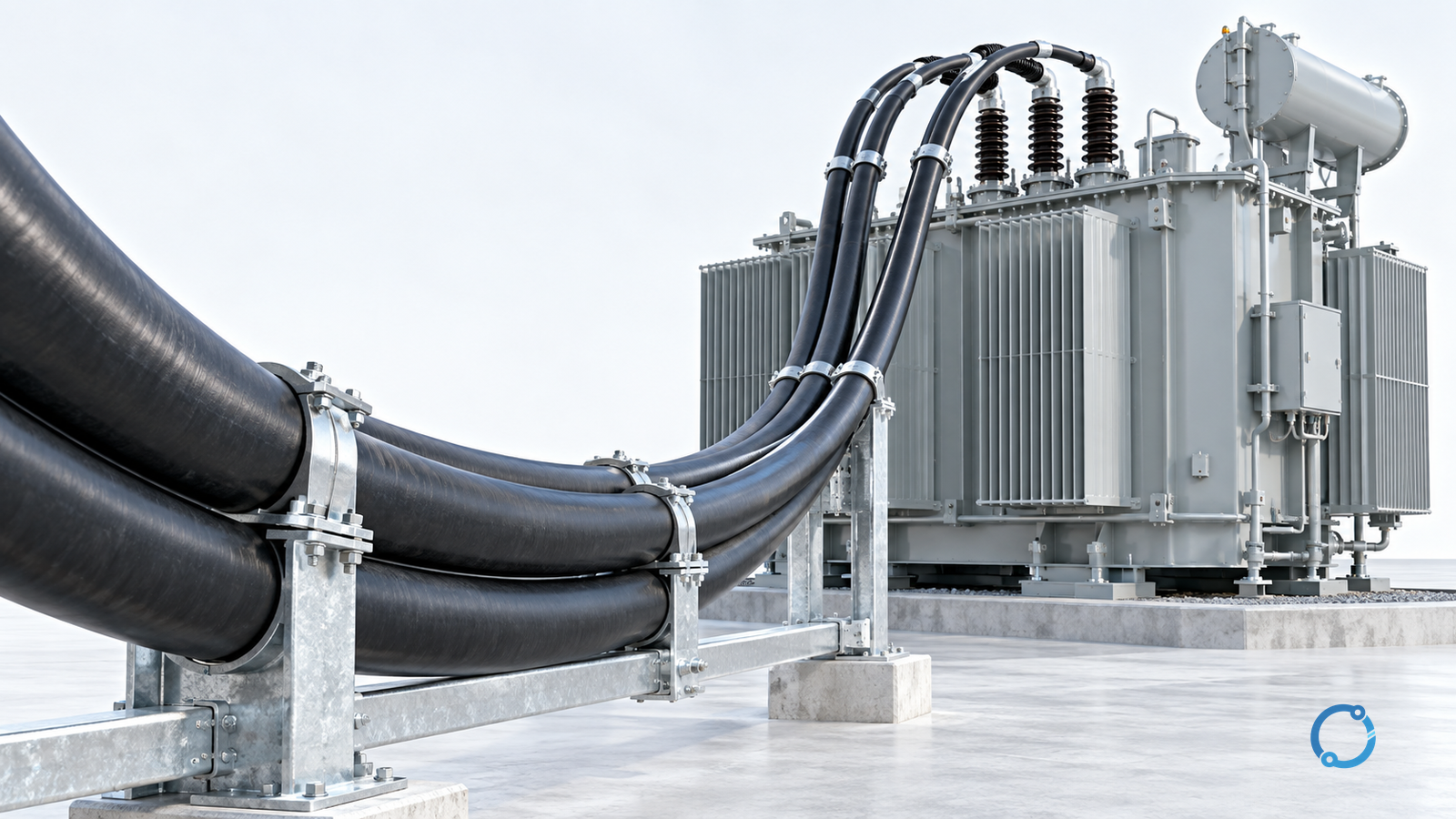
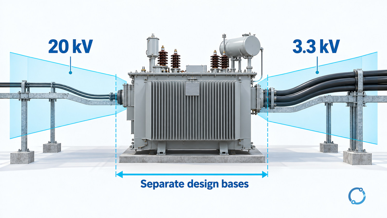
An MV transformer feeder cannot be sized from transformer MVA and an ampacity table alone. First identify which winding the cable serves; then establish insulation duty, route-specific thermal rating, screen bonding and fault withstand. The 20 kV and 3.3 kV sides of the same transformer require separate cable schedules.
This guide uses a hypothetical 12.5 MVA, 20/3.3 kV, balanced three-phase transformer to build that schedule. It does not select a conductor area, accessory or protective setting for an actual installation. Those decisions require the project network study, installation model and qualified design review.
Calculate the winding current, not a single “transformer current”
For three-phase apparent power at the stated line-to-line voltage:
I = S / (√3 × VLL)
| Winding | Inputs | Rated current, rounded |
|---|---|---|
| 20 kV | 12,500,000 VA / (√3 × 20,000 V) | 360.84 A |
| 3.3 kV | 12,500,000 VA / (√3 × 3,300 V) | 2,186.93 A |
Power factor is not inserted again because the input is apparent power in VA, not real power in W. These currents describe rated balanced operation at nominal voltage. They do not include an approved overload duty or establish the installation’s worst operating condition.
Use the actual transformer rating, tap range, permissible loading and operating scenarios to define design current. If a loading study permits more than rated MVA, carry its duration and thermal assumptions into the cable assessment. Do not silently convert an emergency transformer allowance into continuous cable duty.
The much larger secondary current may prompt comparison of parallel cables and another connection architecture. Dividing 2,186.93 A by the number of runs is only a starting allocation: it does not prove equal sharing or that each installed run can carry its allocated current.
Establish a separate voltage-class boundary on each side
A cable’s rated voltage designation must suit conductor-to-earth and conductor-to-conductor duty, maximum system voltage and the network’s earth-fault behavior. “20 kV system” is not, by itself, a complete insulation specification. Record the earthing arrangement, permitted earth-fault duration, insulation coordination and accessory interface requirements.
The public scope of IEC 60502-2:2014 with Amendment 1:2024 covers fixed extruded-insulation power cables with rated voltages from 6 kV to 30 kV. It is relevant to examining the 20 kV cable specification, but its stated scope must not be used as proof of a 3.3 kV cable’s qualification. Confirm the applicable cable standard, rating and supplier evidence separately for the lower-voltage side.
Cable and termination compatibility is also a system decision. A conductor area that satisfies heating may not fit the specified termination range, cable diameter, screen construction or transformer cable box. The MV termination stress-control guide addresses that interface; it is not a substitute for selecting the cable voltage class.
Rate the complete installed route
Prepare an installation model for each route segment: air, tray, duct, trench, buried section and entry into equipment. Include ambient conditions, soil assumptions where applicable, grouping, adjacent heat sources and circuit arrangement. A short unfavorable section can govern a route that otherwise appears generous.
IEC 60287-1-1:2023 addresses steady-state cable current-rating calculations. Its public scope does not provide a universal ampacity for this transformer. The result depends on the cable and installation inputs used in the calculation.
For parallel runs, retain the actual phase arrangement, lengths, conductor construction and connection impedance in the sharing assessment. Check every terminal and bus interface as well as the cable. If a contingency assumes operation with a run unavailable, calculate that scenario explicitly or prohibit it in the operating basis; do not assume spare capacity exists.
For a general low-voltage coordination framework, use the separate feeder cable and circuit-breaker sizing guide. The MV schedule additionally needs screen, bonding and insulation-duty evidence.
Keep conductor duty and metallic-screen duty separate
The phase conductor and metallic screen are not interchangeable fault-current paths. Identify which earth-fault current flows through each screen, sheath or bonding connection and for how long. A phase conductor passing its short-circuit check does not prove that the screen passes its own check.
Evaluate the selected bonding arrangement for circulating losses, induced sheath voltage and accessible interfaces. These effects depend on route geometry and the adopted scheme; “bond both ends” or “bond one end” is not a universal prescription. Include any bonding accessories and their duty in the approved design. CIGRE’s public summary of sheath-bonding design explains these mechanisms. Its formal study focuses on transmission cables at and above 66 kV and notes lower-voltage application of the principles; it is not a ready-made bonding arrangement for this 20 kV example.
Use the prospective fault levels and actual protection clearing-time envelope, including applicable backup operation, to verify withstand. Compare the resulting duty with the specified conductor, screen and accessory evidence. Do not reuse a short-circuit constant or a screen rating from a different cable construction.
Release a side-specific evidence schedule
| Schedule item | Required design evidence | Hold the selection when… |
|---|---|---|
| Winding and operating duty | Side, tap/voltage basis, current and loading scenarios | One current is used for both sides |
| Insulation and accessories | Applicable standard, voltage designation, earth-fault basis and matched interfaces | Nominal system voltage is the only justification |
| Route and parallel runs | Thermal model, limiting segment, phase layout and sharing assessment | A catalogue rating is treated as an installed rating |
| Fault and bonding duty | Phase and earth-fault studies, clearing times, screen/sheath and bonding checks | Only the phase conductor has been checked |
| Equipment connection | Terminal capacity, cable-box constraints and approved connection arrangement | A selected cable cannot be accommodated at an endpoint |
Cross-reference the transformer data in the IEC 60076 specification guide, then reconcile the cable schedule with the protection and connection drawings. Release is justified when both winding schedules close their evidence gaps—not when an MVA calculation produces a plausible current.