
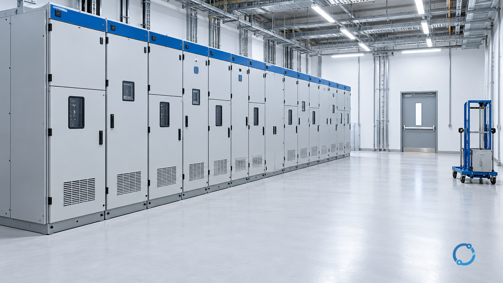
Choose a fixed functional unit when the approved isolation and maintenance plan can establish the required work boundary without moving the device, and the installation provides the access needed for that work. Choose a withdrawable unit when defined service, test and disconnected positions, unit exchange or a smaller work zone are real operational requirements, the racking and removal envelope fits the room, and the assembly’s interlocks, shutters, service continuity and arc boundaries are verified.
Neither choice is universally better. “Fixed” and “withdrawable” describe how a breaker or other functional unit is mounted and moved. They do not, by themselves, establish isolation performance, reliability, maintainability, floor-space needs or personnel safety. Those outcomes depend on the assembly, its declared classifications, the installation and the operating procedure.
This comparison is limited to IEC-oriented prefabricated AC metal-enclosed MV switchgear. The official catalogue scope for IEC 62271-200:2021+AMD1:2024 covers assemblies above 1 kV through 52 kV within its stated conditions. The page identifies the assembly-standard scope; it does not certify a particular product or replace delivered drawings and declarations. For wider equipment context, see OHELE’s guide to switching devices in medium-voltage switchgear.
Start with the maintenance boundary
The useful question is not which construction is more reliable. It is which lets the project establish, verify and restore the required work boundary with acceptable dependence on adjacent equipment.
Define the boundary before comparing layouts:
- Which functional unit must be worked on?
- Which sources, backfeeds and stored-energy sources can reach it?
- Must the busbar, cable terminals or fixed contacts remain energized?
- Which adjacent units must stay available?
- What isolation, absence-of-voltage verification, earthing and access steps are required?
- Which positions, shutters, locks and interlocks form part of the approved procedure?
A fixed unit may have a well-defined isolating arrangement. A withdrawable unit may leave live fixed contacts behind when the movable part is removed. Conversely, a withdrawable unit may support a narrower maintenance boundary, but only if its compartments, service-continuity classification, shutters and procedures support that claim. OHELE’s distribution substation overview shows why source paths and the one-line arrangement belong in this review.
What the two constructions change
In a fixed arrangement, the breaker or other functional unit remains mounted in a fixed position. Its primary connections are not routinely separated by moving the whole unit. Isolation may be provided by separate disconnectors, a switch-disconnector, an upstream or downstream device, or another tested arrangement. A fixed unit is therefore not synonymous with “cannot be isolated” or “cannot be maintained.” Its maintenance method must use the isolation and access arrangement provided by the design.
In a withdrawable arrangement, the functional unit is mounted on a movable carriage, truck or cassette and can move between defined positions. A common scheme provides a service position with main and auxiliary circuits connected, a test position with the main circuit separated while specified auxiliary functions may remain available, and a disconnected position in which the unit is separated further and may be removable. Exact states, travel, contacts and indications are design-specific.
This changes maintenance. A withdrawable unit can be exchanged without dismantling its primary connections, while a fixed unit may require more work within the compartment or a wider isolation boundary. But withdrawal adds moving contacts, shutters, position mechanisms, alignment features and a handling route. A fixed design can be mechanically simpler at the unit interface while requiring separate isolation devices and more in-place work.
“Removable,” “draw-out,” “cassette,” “truck” and “plug-in” may describe different arrangements. Read the drawings and instructions rather than assuming two products use the same positions or definition of “test.”
Fixed-dimension comparison matrix
The matrix holds the evaluation dimensions constant. “Better” is not assigned to either column; every cell states a design tendency that must be confirmed for the actual assembly.
| Evaluation dimension | Fixed functional unit | Withdrawable functional unit | Evidence to verify |
|---|---|---|---|
| Physical arrangement | Unit remains in a fixed mounting; primary connections are not routinely separated by moving it | Unit moves on a carriage or cassette between defined positions | Approved single line, arrangement and unit drawings |
| Normal switching | Device operates in place; isolation is a separate designed function or state | Device can operate in service and, where designed, test position; movement is separate | Operating sequence, position logic and functional tests |
| Isolation for unit work | Depends on available disconnectors, isolation points and earthing | Main circuit separates with unit position; fixed contacts may remain live | Isolation diagram, position definition, shutter arrangement and voltage-verification method |
| Adjacent units | May require a wider busbar or cable-side boundary unless the assembly provides otherwise | May allow work on the unit while others remain available, subject to assembly classification | Loss-of-service continuity (LSC) declaration, partitions, access rules and outage plan |
| Access and handling | In-place work may need cover removal, rear access, lifting or component extraction | Needs door swing, racking travel, unit removal, lifting, storage and a handling route | Complete operating envelope in the approved room layout |
| Service, test and disconnected states | Established by installed switching devices and indications | Established by unit position plus relevant device and control states | Position table, mechanical/electrical indication and instructions |
| Interlocks and shutters | May coordinate breakers, disconnectors, earthing switches and access covers | Commonly coordinate breaker state, movement, shutters, earthing and access; logic varies | Interlock schedule, keys, function-test results and tamper controls |
| Fault and arc boundary | Defined by compartments, barriers, pressure relief and tested arrangement | Same assembly-level issue, plus moving contacts, shutters and positions | Partition, LSC and internal-arc declarations for the exact arrangement |
| Environment | Fixed interfaces may reduce routine moving-contact concerns, but insulation still faces site conditions | Moving contacts, alignment, lubricants and shutters need a compatible regime | Ambient, humidity, contamination, corrosion and ingress requirements |
| Reliability | No universal advantage; fixed connections and separate isolators have their own failure modes | No universal advantage; racking, alignment, shutters and position mechanisms add different modes | Failure history, inspection findings, duty and supportability data |
| Maintenance and spares | May need more in-place work and wider isolation; fewer handling steps | May support spare-unit exchange, but the spare and restoration must be compatible | Tooling, compatible-spare control and restoration procedure |
| Lifecycle | Compare outage scope, access cost, labour, parts and future modification | Compare unit cost, spare inventory, floor area, handling, training and disposal | Whole-life assumptions, quotations and outage consequences |
Maintenance isolation and the next unit
Maintenance on either construction begins with a hazardous-energy and work-boundary review. A withdrawable unit does not create an exception. It may be racked out while the cable side, busbar side, auxiliary supply, control circuits, stored spring energy, capacitors or induced voltage still present hazards. A fixed unit can be equally hazardous if isolation points are not identified or the compartment is opened without required controls.
For a withdrawable unit, answer three different questions:
- Is the breaker or switching device in the required state for movement?
- Has the unit reached the specified test or disconnected position with the main circuit separated?
- Has the fixed portion been isolated, verified, earthed where required and placed under authorized work control before anyone treats it as safe to touch?
A position mark proves only the position its mechanism indicates. A closed shutter covers fixed contacts but does not prove they are de-energized. A breaker-open indication does not prove absence of voltage on either side. For covered U.S. general-industry work, OSHA 1910.333 addresses de-energization and verification, while OSHA 1910.147 addresses hazardous-energy control. Check their scope and local equivalents.
For a fixed unit, the isolation plan may use upstream and downstream devices, a disconnector, a removable link or another engineered means. Work may require a bus-section outage, cable-side isolation or a larger portion of the board. That is not automatically a disadvantage, because the assembly may provide clear isolation and earthing with fewer routine moving interfaces. The design must be compared on the actual switching sequence, not on a promise that fixed equipment needs no isolation.
Adjacent-unit availability is controlled by loss-of-service continuity and partition arrangements, not by the construction label alone. One withdrawable unit may be maintainable while others remain in service; another arrangement may require the same busbar outage as a fixed unit. A fixed unit with adequate partitioning and dedicated isolation may also support a narrower boundary than a poorly arranged withdrawable assembly. Ask for the service-continuity category, compartment arrangement, accessible sides and operating restrictions for the exact configuration.
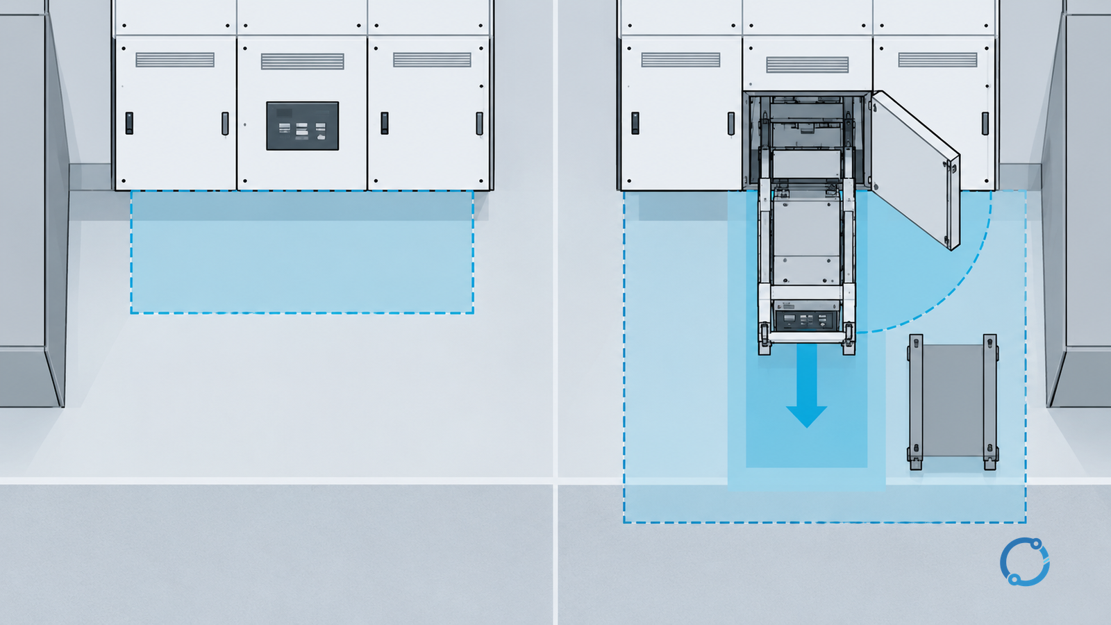
Floor space is more than the footprint
Floor-space comparisons fail when they measure only the equipment outline. For a withdrawable unit, the complete envelope can include door swing, racking tools, carriage travel, removal onto a floor truck, lifting, temporary storage, personnel egress and a route to a safe storage area. A layout that allows the door to open but not the unit to be removed is incomplete. Aisle width, floor loading, thresholds, ramps and overhead services can all affect handling.
For a fixed unit, the room may not need withdrawal travel, but it may need space for opening covers, reaching rear connections, using test equipment, lifting components and establishing a work zone. Rear access may be essential for cable termination even when normal operation is from the front. A fixed design can sometimes reduce the operating aisle requirement, but that is a project conclusion.
Use assembly drawings, installation instructions and locally accepted access requirements to establish dimensions. This article gives no universal clearance, aisle width, racking distance or door-swing value because they depend on the equipment, voltage, handling method and room.
Positions, interlocks and shutters
A withdrawable unit’s value depends on whether its position and interlock scheme is complete, visible and testable. Typical functions may prevent movement while the breaker is closed, prevent closure outside a permitted position, control shutters over fixed contacts, coordinate earthing and compartment access, retain the unit in position, distinguish service/test/disconnected states, and ensure protection and control behave correctly in each state.
That is a design checklist, not a claim that every product uses the same logic. The approved interlock schedule and actual function test determine what is provided. An interlock shown on a drawing but never demonstrated after installation is an open item. A defeat device, temporary bypass or maintenance mode must be controlled by an authorized procedure and restored before energization.
A fixed arrangement has its own interlock questions: breaker-to-disconnector sequence, disconnector-to-earthing-switch sequence, access-cover interlocks, key transfer and remote-control permissives. It may have no racking mechanism, but it can still have a complex switching sequence. Count the required operations and their consequences, not merely whether a truck is present.
Shutters are mechanical covers for fixed contacts, not portable insulating barriers, lockout devices or substitutes for voltage verification. Their position should be part of the designed sequence, and their condition should be inspected for deformation, contamination, loose linkage or obstruction. Do not reach into a shutter opening to test a contact or assume that a closed shutter makes the compartment safe.
Position terminology also needs verification. “Service,” “test,” “disconnected,” “isolated” and “withdrawn” may not mean the same thing across products or specifications. Require a position table stating the main-circuit and auxiliary-circuit conditions, permitted operations, interlock state and access condition for each position. That is more useful than a label on a mimic panel.
Fault, arc and compartment boundaries
Both constructions can be installed in metal-enclosed assemblies with compartments, barriers and pressure relief. Construction does not replace assembly-level questions:
- Which compartments can remain energized during permitted access?
- What partition class applies, and which barriers are metallic or insulating?
- What loss-of-service continuity category is declared?
- Is an internal-arc classification provided, for which accessible sides, current and duration?
- Does the classification and instruction cover operation, testing and maintenance positions?
- Where are pressure-relief outlets, and how does the room deal with exhaust?
- What fault current and clearing time form the assessment basis?
A withdrawable unit adds moving contacts, shutters and position openings to the assembly. A fixed unit may avoid that movement interface but can require separate disconnectors or a larger isolation boundary. Neither construction should be credited with an arc rating not declared for its exact compartment arrangement. An internal-arc classification is evidence for a defined tested configuration; it does not guarantee that every fault, open door, removed unit or maintenance state is safe.
Compartment and arc evidence also interacts with the site’s safe-work and arc-flash assessment. OHELE’s MV switchgear commissioning release covers the separate pre-energization evidence boundary. For breaker-specific duties, the MV circuit-breaker ratings guide keeps making, breaking, short-time withstand and operating-sequence questions separate. If remote racking or operation is proposed, establish what it controls and what remains manual. Remote operation changes exposure; it does not remove position verification, interlock testing, work permits or a controlled isolation boundary.
Environment, reliability and lifecycle
Dust, humidity, condensation, corrosive gases, salt, vibration and temperature changes can degrade insulation, contacts and mechanisms. A withdrawable design introduces sliding or plug-in contacts, alignment features, shutter linkages and lubricated mechanisms that need a compatible environment and inspection regime. A fixed design may have fewer routine moving interfaces, but its connections, insulation, separate isolating devices and compartment access still need protection and maintenance.
Reliability claims should name a failure mode and duty. Candidates include contact wear, joint overheating, insulation tracking, mechanism seizure, shutter damage, interlock wear, auxiliary-contact failure and position-indication error. No universal failure rate or mean time between failures is used here because any such value would depend on design, population, loading, environment, maintenance and reporting practice.
Maintainability follows the same logic. A withdrawable unit can shorten work on a failed unit only when a compatible spare is available, the removal route is clear, the fixed portion can be isolated, replacement alignment is correct, and the restored unit is tested. A physically similar spare with different ratings, auxiliary contacts, wiring or interlock geometry is not interchangeable. A fixed unit can be maintained in place with fewer handling steps, but the work may require a larger outage and more reassembly. OHELE’s guide to aging switchgear repair, retrofit or replacement covers the separate lifecycle intervention decision.
Lifecycle evaluation should compare the whole maintenance system: floor area and building cost; handling equipment and spare storage; outage scope; inspection and functional-test labour; training; spare availability; future modification; end-of-life replacement; and the cost of an incorrect operation or defeated interlock. These factors can point in different directions. A facility with expensive lost production may value a verified spare-unit strategy; a facility with low switching frequency and robust in-place isolation may prefer the simpler fixed interface. Neither preference should override an unresolved safety or classification question.
A conditional selection workflow
- Freeze the system boundary. Record the single line, voltage, frequency, fault study, protection clearing time, source and backfeed paths, bus arrangement and future modes. Confirm which units must remain available.
- Define the maintenance method. For each unit, state how it will be isolated, verified, earthed where required, accessed and restored. Separate normal switching, planned maintenance and emergency intervention.
- Set the continuity objective. Identify the permissible outage of adjacent units and the required service-continuity configuration. Do not accept “withdrawable means less downtime” as a generic claim.
- Build the physical access case. Obtain the room layout and complete operating envelope: door swing, racking travel, unit removal, lifting, storage, rear access, egress and test-equipment space.
- Specify environment and inspection. Record ambient, humidity, contamination, corrosion, ventilation and operating frequency. Match inspection to the contacts, shutters and mechanisms actually installed.
- Define positions and interlocks. Require a position table for service, test and disconnected states, the operations permitted in each, and the interlocks to be demonstrated at commissioning.
- Set assembly classifications. Establish the required partition, service-continuity and internal-arc basis for the exact arrangement, including accessible sides, installation assumptions and maintenance positions.
- Compare lifecycle consequences. Use project-specific outage, spares, handling, maintenance and training assumptions. Do not insert an unsupported reliability number to make the comparison look quantitative.
- Verify the evidence. Match drawings, declarations, instructions and test records to the exact assembly revision. A catalogue page or device certificate cannot stand in for the complete assembly.
- Record the decision and holds. State why the construction fits, which alternatives were rejected, and what must close before design freeze, manufacture, installation or energization.
Hold conditions
Place the decision on hold when any of these conditions applies:
- the single line, source paths or backfeed conditions are unapproved;
- the fault current, clearing time or arc basis is unknown;
- required continuity, partition or internal-arc classifications are undeclared for the exact assembly;
- the layout lacks the full withdrawal, lifting, storage and access envelope;
- the position table, shutter behavior or interlock schedule is unreviewed;
- the method for isolating and verifying fixed contacts or the cable side is undefined;
- the proposed spare is not confirmed compatible;
- restoration and authorized-release evidence is incomplete;
- the site’s isolation, lockout/tagout, earthing and qualified-person procedures are not established.
These are engineering holds, not reasons to select the other construction automatically. A fixed scheme with an unresolved isolation method is not safer than a withdrawable scheme with a verified one, and a withdrawable scheme with an unverified racking envelope is not more maintainable than a fixed scheme with a clear in-place procedure.
Conclusion
The defensible choice is conditional. Fixed construction can be appropriate when the isolation and earthing arrangement is explicit, in-place maintenance is practical, and the assembly provides the compartment and continuity evidence the project needs. Withdrawable construction can be appropriate when defined positions and unit exchange solve a real operating problem, the room accommodates the full handling envelope, and the assembly’s interlocks, shutters, service-continuity and arc boundaries are demonstrated.
Do not select either construction from a brochure adjective. Start with the work boundary and continuity requirement, then compare the exact layouts, positions, interlocks and assembly declarations. This is an IEC-oriented comparison; North American projects must map requirements to the standards, codes and authority having jurisdiction that actually apply, without treating IEC terms as interchangeable with ANSI, IEEE or UL terms.
Only qualified, authorized personnel should operate, isolate, earth, test or maintain MV switchgear under approved site procedures. This comparison does not authorize energized work, backfeed operation, interlock defeat or entry into an energized compartment.
Sources
- IEC 62271-200:2021+AMD1:2024 — AC metal-enclosed switchgear and controlgear
- IEC 62271-1:2017+A1:2021 — common specifications for AC switchgear and controlgear
- IEC 62271-100:2021 — AC circuit breakers
- IEC 62271-102:2018 — AC disconnectors and earthing switches
- OSHA 1910.333 — selection and use of electrical work practices
- OSHA 1910.147 — control of hazardous energy