
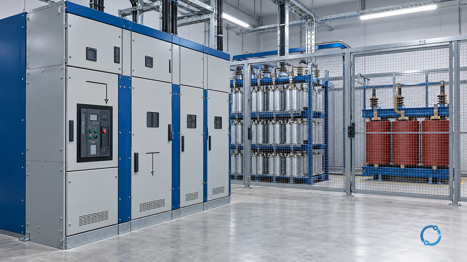
A medium-voltage circuit breaker for a power-factor-correction capacitor bank cannot be selected from feeder current alone. The breaker must make, carry and interrupt a bank under conditions that include capacitive current, energization inrush, back-to-back switching, recovery voltage, possible restrike and the surrounding fault and protection system. A device that is acceptable for a motor or distribution feeder can still be poorly matched to a capacitor bank.
Start with a qualified-person boundary. Medium-voltage capacitors can retain hazardous energy after the supply is removed, and the switching equipment can expose stored energy, charged conductors, automation outputs and back-feed paths. Isolation, absence-of-voltage verification, capacitance discharge, grounding and work-permit control must follow the site’s approved procedure. In the U.S. general-industry context, 29 CFR 1910.333 provides a named de-energization and qualified-person boundary; it is not a universal design standard.
This article explains the inputs that should be taken to a breaker specification and the evidence that must come back from the equipment supplier and system study. It does not calculate the bank, approve a switching device or replace the applicable IEC product, system-study and commissioning requirements.
A normal feeder breaker is not automatically a capacitor breaker
A distribution feeder breaker is usually selected around load current, system short-circuit current, insulation, control and protection. A capacitor bank adds a different electrical duty:
- the bank draws leading current and its continuous current depends on the actual applied voltage and bank configuration;
- energizing an uncharged bank can produce a high-frequency inrush current limited mainly by the system and any series reactor;
- switching one bank while another is already energized can produce a more severe back-to-back inrush condition;
- interrupting capacitive current creates a recovery voltage across the opening breaker;
- a restrike during or after interruption can produce an overvoltage condition that affects the bank, breaker, transformers, cables and arresters;
- capacitor units may retain charge after separation and can feed fault or switching conditions through parallel paths;
- the bank’s capacitance and step arrangement can change the fault-current contribution and protection response.
The breaker is therefore one part of a capacitor-bank switching system. Its selection must be consistent with the bank design, reactor or damping arrangement, protection scheme, earthing method and operating sequence.
Define the system and bank before reviewing a breaker catalog
A specification begins with a controlled input list. The exact document set depends on the project, but the following data should be available before comparing products:
- nominal system voltage, maximum operating voltage and frequency;
- three-phase and single-phase fault levels at the point of connection;
- system earthing method and transformer or generator neutral treatment;
- insulation-coordination requirements and expected temporary overvoltages;
- bank rated power, rated voltage, configuration and number of steps;
- capacitor-unit arrangement, parallel units per phase and neutral connection;
- series reactor or damping equipment, if used;
- expected harmonics and background distortion;
- measured or calculated continuous current for each step and the complete bank;
- prospective short-circuit and peak currents with the bank in the relevant operating state;
- required capacitive making and breaking capability;
- protection, interlocking and control architecture;
- operating sequence, restart interval and maintenance access;
- the product standards and project specification that will govern acceptance.
“Capacitor bank, 10 MVAr” is not a selection input by itself. The same apparent bank power can lead to different voltage, current and switching duties depending on bank topology, step arrangement, reactor design and system conditions.
The capacitor-bank panel functional diagram provides a low-voltage conceptual architecture; it illustrates the role of the bank and switching path but does not supply a medium-voltage breaker rating. Why raise power factor explains the upstream objective. Neither article should be substituted for the project single-line diagram and capacitor-bank data.
Use an eight-gate selection flow
The sequence below keeps different ratings from being collapsed into one current number.
Gate 1: define the scope and design authority
Record whether the work is a new bank, a breaker replacement on an existing bank, a step addition, a protection upgrade or a study of an existing installation. Identify the design authority for the capacitor bank, switchgear, earthing and protection. A breaker supplier can provide product data, but it does not inherit responsibility for an incomplete system design.
Confirm the system state that will be modelled. Maximum fault current and minimum fault current may support different checks. Parallel transformers, generator operation, busbar ties, future expansion and disconnected sections can change the duty seen by the breaker.
Gate 2: establish voltage and earthing duty
Separate nominal system voltage from the equipment’s maximum voltage and insulation requirement. The breaker, capacitor units, reactors, cables, voltage transformers and surge arresters must be coordinated for the same system and overvoltage environment.
Earthing affects:
- insulation coordination and temporary overvoltage exposure;
- phase-to-earth recovery voltage after interruption;
- protection and sensitive earth-fault behaviour;
- the consequences of a single-phase restrike;
- the treatment of neutral imbalance and capacitor protection;
- the permissible operating and switching states of the bank.
Do not assume that an isolated or resistance-earthed system behaves like a solidly earthed system. If the system is unearthed, resonant-earthed or otherwise special, the project study must explicitly cover the resulting voltage and protection duties.
Gate 3: resolve the bank topology and current basis
Document the bank’s rated kvar or Mvar, rated voltage, actual bus voltage, phase connection, number of parallel units, number of steps and series reactor arrangement. Calculate the continuous current using consistent units:
For a balanced three-phase bank:
I_bank ≈ Q / (√3 × V_LL)
where Q and V_LL must refer to the same applied-voltage basis. If the capacitor-unit rated voltage is not the actual bus voltage, do not insert the nameplate voltage and bank power into the formula without reconciling the difference. The capacitor’s voltage, reactive output and current change together.
Then add the project’s verified voltage tolerance, harmonic current and design margin according to the applicable bank and breaker requirements. Do not invent a universal multiplier such as a fixed percentage over nominal bank current. Harmonic current can be significant when capacitors are exposed to distorted voltage; its path and magnitude require the bank design or a harmonic study.
The current basis should be stated separately for:
- a single step energization;
- all steps energized;
- operation with one capacitor unit or branch out of service;
- the maximum credible harmonic condition;
- fault contributions from the bank.
Medium-voltage circuit-breaker ratings explains why rated current, short-circuit breaking current, making current and switching classes answer different questions. A catalog table cannot be accepted until the proposed breaker’s complete rating set is mapped to the bank record.
Gate 4: verify continuous thermal and voltage duty
The breaker’s continuous-current path includes its terminals, contacts, bushings and enclosure environment. Consider ambient temperature, enclosure heating, altitude, solar exposure, forced ventilation, cable or busbar connections and the installation arrangement. The capacitor bank may be one heat source among several.
Confirm that the continuous-current basis used for the breaker matches the actual bank current plus the applicable harmonic content and design tolerance. A breaker cannot be approved merely because the nominal bank current is lower than its rated current. The product instructions and project design should state how the installed conditions are treated.
Check: do not assume that a capacitor bank at apparent no-load is thermally inactive. It can carry current whenever it is energized, and that current may continue after the plant load is removed. Capacitor switching must remain safe and stable at the lightest and heaviest credible plant conditions.
Gate 5: check fault making and breaking with the bank in service
Obtain the prospective short-circuit current and peak current at the breaker location from a system study that includes the operating states relevant to the bank. The condenser bank’s stored energy may contribute to the fault current and to the recovery condition; the study must model the applicable bank and network.
The breaker evidence should demonstrate:
- rated short-circuit breaking capability for the relevant fault type and voltage;
- making capability for the prospective peak current;
- short-time withstand and protection coordination where the protection scheme requires it;
- contact and terminal thermal duty during the specified fault clearance;
- compatibility with the neutral and earthing arrangement;
- any required enclosure or arc-resistant rating for the installation.
Do not combine a breaker making rating with a different catalog rating or assume that the highest quoted fault current covers every switching state. The applicable IEC product standard and project study define the comparisons.
Gate 6: establish capacitive making and breaking duty
The breaker must be suitable for energizing and de-energizing the capacitor bank, not merely for carrying its load current. The specification should identify:
- the number of bank steps and whether switching is selective or group-operated;
- maximum inrush current and its frequency, with the assumptions behind those values;
- back-to-back switching cases and the effect of existing energized steps;
- the series reactor, damping or current-limiting device;
- required capacitive switching capability and test evidence;
- the operating sequence and permissible time between close and open operations;
- capacitor-discharge and reclose restrictions.
Inrush is a high-frequency current path through the breaker, capacitor units, cables, busbars and reactor. A reactor selected only to tune the bank may not provide the damping or current limitation needed for the breaker’s switching duty. Conversely, adding a reactor changes the bank voltage and reactive output, so the selection must be coordinated rather than treated as a retrofit detail.
The switching-device role comparison and circuit-breaker versus contactor switching duty help separate device functions. They do not provide a universal capacitor-switching rating. The breaker’s actual assigned switching duty and test evidence remain mandatory.
Gate 7: check recovery voltage, restrike and overvoltage coordination
After the breaker interrupts capacitive current, the bank side can remain charged while the source side changes. The resulting recovery voltage stresses the interrupter and can create a restrike path. Multiple restrikes may generate high overvoltages that affect capacitor units, reactors, cables, transformers, arresters and adjacent switchgear.
The project record should state:
- system and bank earthing;
- expected recovery-voltage waveform and source/bank voltage relationship;
- breaker interruption technology and the manufacturer’s applicable evidence;
- any grading capacitor, reactor or damping arrangement;
- surge-arrester and insulation-coordination basis;
- protection behaviour if restrike or overvoltage occurs;
- operating and maintenance actions after an abnormal switching event.
This is a system-study boundary. The breaker nameplate does not contain the bank’s recovery voltage or restrike consequence, and a generic statement that a product is “capacitor-rated” does not prove suitability for the actual overvoltage and earthing case.
Gate 8: coordinate protection, interlocks and commissioning
The breaker must operate with a protection and control scheme that covers:
- overcurrent and short-circuit protection;
- capacitor unbalance or differential protection where provided;
- overvoltage and undervoltage conditions;
- bank discharge, reclose and restart logic;
- breaker failure or failure-to-close indication;
- step-control interlocks and operator selection;
- earthing-switch and door or compartment interlocks;
- remote and local control priorities;
- event recording and switching counters.
A capacitor bank can remain charged after the breaker opens, so the operating sequence must account for discharge time and verification. Do not treat a closed earthing switch, an opened breaker or a control indication as proof that every capacitor path is safe. Follow the approved grounding and test procedure.
Build a selection evidence matrix
Use a single matrix to compare the bank requirement with the proposed breaker. The exact rating values and test classes must come from the applicable project specification and product standards.
| Duty or evidence | Bank/system input | Breaker evidence | Remaining action |
|---|---|---|---|
| Maximum system voltage | System study and insulation basis | Rated voltage and insulation data | Confirm temporary overvoltage case |
| Continuous current | Bank voltage, Mvar, steps, harmonics and tolerance | Assigned continuous-current capability | Verify installed thermal environment |
| Fault breaking | Prospective fault current by state | Rated short-circuit breaking capability | Reconcile with system and protection study |
| Peak making | Prospective peak current | Rated making capability | Check fault and bank contribution |
| Capacitive making | Inrush and back-to-back cases | Capacitive switching evidence | Verify reactor and step sequence |
| Capacitive breaking | Bank current and recovery voltage | Capacitive breaking evidence | Confirm restrike/overvoltage consequences |
| Insulation | Earthing and temporary overvoltage | Insulation level and clearances | Coordinate with cables, reactors and arresters |
| Protection | Bank and system protection scheme | Trip, auxiliary and failure interfaces | Prove logic and settings |
| Operation | Switching sequence and restart policy | Mechanical and electrical operating limits | Test interlocks and event records |
If a cell cannot be filled with controlled evidence, it is an open design item. It is not safe to fill it with an assumed rating.
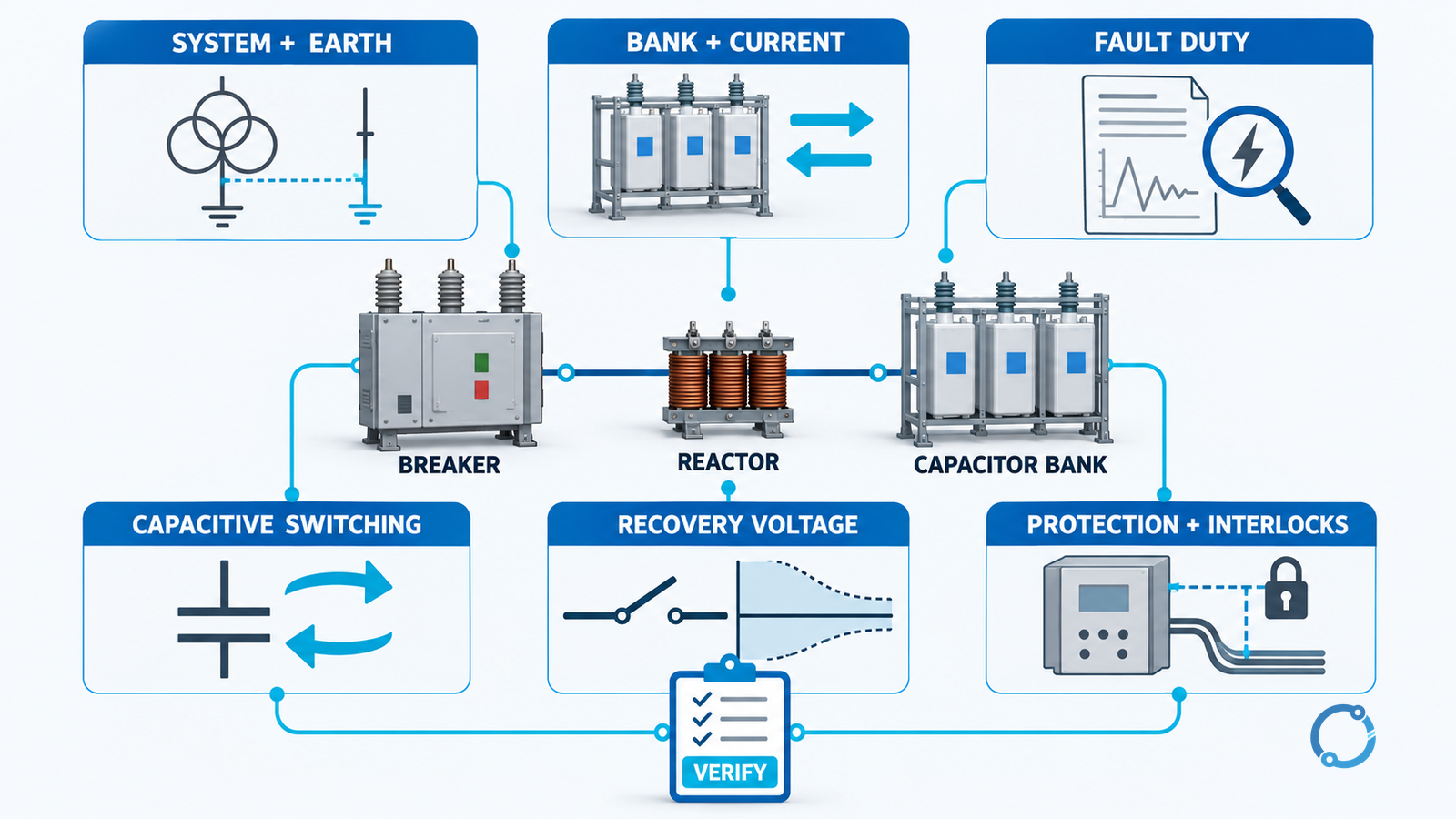
What to request from the breaker supplier
The request should be specific enough that the supplier answers the actual duty rather than a generic product question. Depending on the project, request:
- complete product identity and applicable standard editions;
- rated voltage, insulation level, frequency and continuous current;
- short-circuit making and breaking ratings;
- capacitive switching classification or demonstrated capability;
- recovery-voltage and restrike-related application information;
- operating mechanism and electrical endurance information;
- opening and closing time data where needed for protection and mechanical coordination;
- control, auxiliary, interlock and test facilities;
- installation environment and enclosure compatibility;
- type-test evidence and routine-test records;
- earthing-switch and contact-position indications;
- maintenance, inspection and spare-parts information;
- project-specific limitations or conditions attached to the rating.
A product standard’s existence does not automatically certify a product. The equipment’s declared ratings, the actual test report and the project review must agree.
Commission and release the bank as a system
Before energization, confirm:
- the installed breaker matches the approved specification;
- nameplate and commissioning records match the source documents;
- the bank, reactor, cables and earthing arrangement match the design assumed in the study;
- protection settings and CT or VT polarity are proven;
- the discharge and restart logic is understood and tested;
- all compartment and earthing interlocks function as specified;
- manual, local and remote controls have defined authority;
- the first-close and step-switching sequence is controlled;
- voltage, current, power, harmonic and event data are recorded;
- any abnormal restrike, overvoltage, inrush or protection indication has a defined response.
Commissioning should verify the complete switching system, not only breaker operation. Record the actual bank step sequence, measured current and voltage, protection operation and status indications. Where the design permits, compare staged energization results with the study assumptions. Unexpected current, voltage distortion, capacitor unbalance, noise, vibration or breaker behaviour is a reason to hold acceptance while the cause is investigated.
The first loaded checks should include the operating states that matter: light plant load, high plant load, one step, all steps and the credible back-to-back sequence. The exact tests and acceptance values belong to the approved commissioning programme and manufacturer instructions.
What the breaker record should say
A defensible release record is concise:
Breaker Q-01 is specified for the documented capacitor-bank voltage, earthing, continuous-current, fault, making, capacitive-breaking and recovery duties. Its assigned ratings and test evidence cover the stated operating states. The series reactor, protection, discharge, interlock and staged commissioning evidence are recorded. The breaker is not released for a bank configuration outside this record.
That statement does not pretend that a catalog selection completed the design. It shows that the breaker was selected as part of the whole bank and switching system.
Common selection errors
- choosing a breaker from continuous current alone;
- using the capacitor nameplate current without correcting for actual voltage;
- assuming that a higher fault rating proves capacitive switching capability;
- omitting the smaller inrush-inducing step that is energized when another bank is already in service;
- treating an upstream reactor as a universal fix without checking the bank tuning and voltage;
- accepting a generic “capacitor” label without test evidence for the actual duty;
- ignoring recovery voltage and single-phase restrike because the breaker normally opens all three phases;
- assuming the protection study and breaker selection are independent;
- releasing a bank without a controlled step sequence and post-event record.
Sources
- IEC 62271-1:2017+AMD1:2021: High-voltage switchgear and controlgear – Part 1: Common specifications, published 2021, consolidated edition.
- IEC 62271-100:2021+AMD1:2024: High-voltage switchgear and controlgear – Part 100: Alternating-current circuit-breakers, published 2024, consolidated edition.
- IEC 60871-1:2014: Shunt capacitors for AC power systems having a rated voltage above 1,000 V – Part 1: General, published 2014, edition 4.
- 29 CFR 1910.333: Selection and use of work practices, accessed 2026-10-28. This is a U.S. general-industry occupational-safety rule, not a universal IEC design standard.