Short Answer
A thyristor is a semiconductor switch that uses internal feedback to sustain conduction. The conventional silicon-controlled rectifier (SCR) is a thyristor that carries load current in one direction. A gate current pulse can start conduction when the anode is positive relative to the cathode. Once the SCR has latched, anode current sustains conduction after the pulse ends.
The gate sets the start of conduction. The main circuit supplies the conditions for turn-off by reducing anode current below the holding current and allowing the device to recover. That split between turn-on and turn-off explains why an SCR works differently in AC and DC circuits.
The SCR Symbol and Its Three Terminals
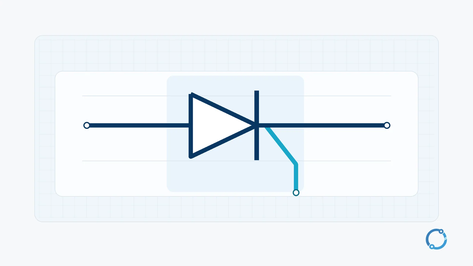
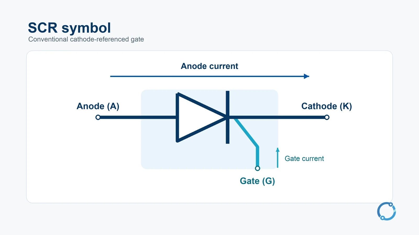
An SCR symbol has the anode and cathode of a rectifier plus a gate lead on the cathode side. Anode (A) and cathode (K) carry the main current. Gate (G) is the trigger input. In the conventional cathode-referenced device shown here, the drive sends current into the gate and returns through the cathode. The trigger is defined relative to K, which can sit at a different potential from the controller’s ground.
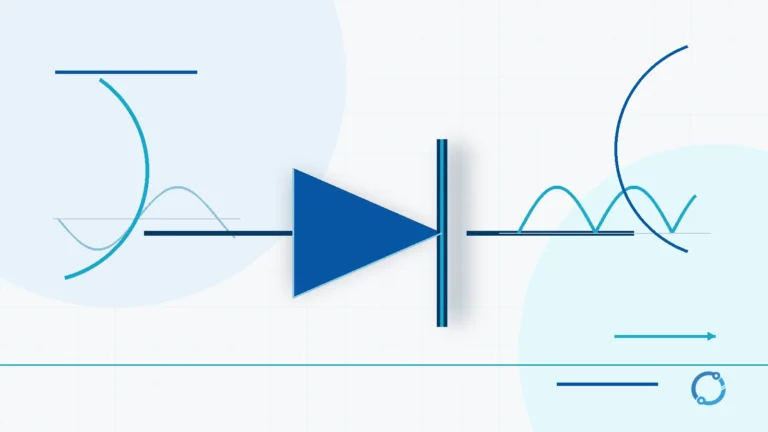
A diode conducts when its forward bias is sufficient for the circuit to draw appreciable current. A conventional SCR can remain off even when its anode is positive, within its forward blocking range. That state is called forward blocking. A suitable firing pulse changes its state while the voltage is still forward. With the opposite main-terminal polarity, a reverse-blocking SCR blocks reverse voltage within its rating. For the behavior of the two-terminal device, see how a diode works.
How a Gate Pulse Triggers and Latches an SCR
A conventional SCR uses four alternating semiconductor layers, arranged P-N-P-N. In its forward-blocking state, the middle junction blocks the main current. Applying a positive gate current relative to the cathode initiates conduction. The gate drive needs sufficient current and duration under the conditions in which the device is being fired. The load supply and its circuit then determine how much main current can flow.
Think of the internal structure as two coupled transistor stages. Current from each stage reinforces the other. The gate pulse starts that feedback, and sufficient anode current sustains it after the gate pulse is withdrawn. This is the physical basis of latching. The two-transistor picture is an equivalent model for one PNPN device.
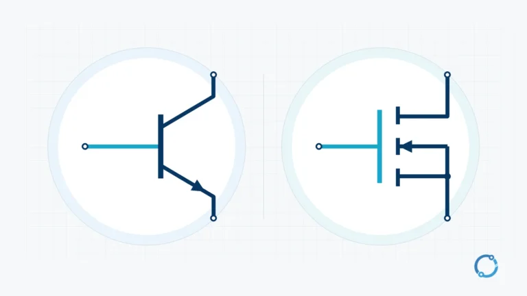
Both an SCR and a transistor can use a small signal to control a larger current path. In a typical MOSFET switch, the gate voltage controls whether the channel remains on. In an SCR, the gate pulse can end while the main path stays on. The anode current supplies the feedback that the device needs. For the transistor side of that distinction, see how BJT and MOSFET switching works.
Latching Current and Holding Current
Gate trigger current refers to the control input. Latching current and holding current refer to the main anode path at different moments. Reading the three as interchangeable values can make a circuit look as if it has triggered successfully even though it loses conduction as soon as the gate pulse ends.
| Quantity | Where it flows | What it tells you |
|---|---|---|
| Gate trigger current, IGT | Gate to cathode | The gate current required to initiate turn-on under specified test conditions. |
| Latching current, IL | Anode to cathode | The minimum main current needed just after turn-on for conduction to persist when the gate drive is removed under the stated conditions. |
| Holding current, IH | Anode to cathode | The minimum main current that sustains an already latched state after the gate drive has ended. |
Latching current is typically higher than holding current. Suppose anode current lies between those two levels. If it reaches only that level before the gate pulse ends, the SCR can drop out. If the SCR has already latched at a higher current and then falls to that same level, it can keep conducting. The history of the current matters because establishing the latch and maintaining it require different conditions. College of Engineering Trivandrum notes on latching and holding current
An inductive load can make the difference visible. Its current may rise slowly enough that a short gate pulse ends before the anode current reaches the latching level. A circuit can also miss latching when the available load current is too small throughout the pulse. In either case, gate current by itself tells you only that a firing attempt was made. The anode current trace tells you whether it took hold.
Reading the SCR Conduction Waveform
Consider one SCR in series with a resistive load on a sine-wave supply. Early in the positive half-cycle, the SCR blocks and the anode current stays near zero. The gate pulse arrives at the firing point. The SCR starts to conduct, and anode current in this simplified resistive example follows the remaining portion of the positive supply wave.
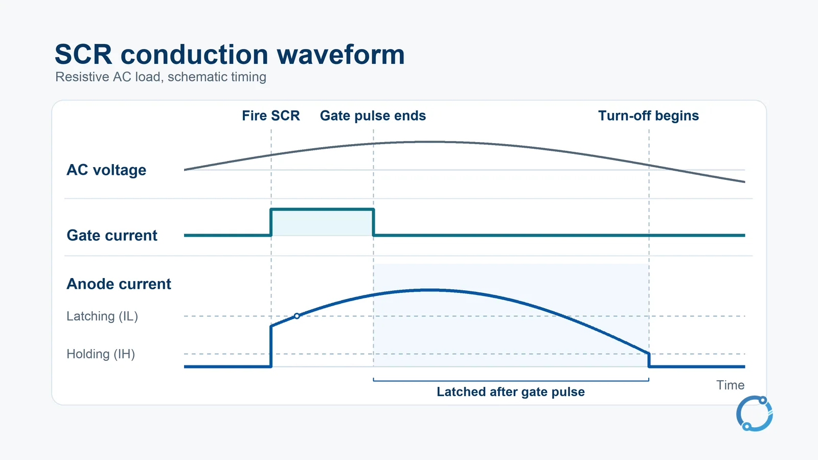
Read the aligned traces from left to right. The gate trace rises first, and the anode trace reaches the latching level while the pulse is present. The gate trace then returns to its baseline while the anode trace continues. Turn-off begins near the end of the positive half-cycle, as anode current reaches the holding boundary and collapses. The reverse half-cycle gives the device time to recover in this circuit. The drawing omits brief switching and recovery transients.
The firing angle describes how far into the AC cycle the gate pulse arrives, measured from the forward half-cycle’s start in this example. A later successful firing leaves a shorter portion of the positive half-cycle for conduction and delivers less energy to the same resistive load. That is how phase-controlled rectification regulates the output. The shape depends on the load, so use this waveform as a resistive example.
How an SCR Turns Off in AC and DC Circuits
An ordinary SCR turns off when its main current drops below the holding level long enough for conduction to cease and the device to recover. Bringing the current through the device to an end is called commutation. The circuit must also give the device time to regain forward blocking before applying forward voltage again. Charge left inside the device makes current extinction and recovery distinct events. If forward voltage returns too early, the SCR can resume conduction without another gate pulse. University of Pittsburgh discussion of SCR turn-off and recovery
In a line-commutated AC circuit, the source and load bring the current through the SCR down naturally, and the circuit provides a recovery interval. With the resistive load shown above, turn-off takes place close to the supply voltage zero crossing. With an inductive load, the current can continue after that crossing. To understand when turn-off happens, follow the current through the SCR and the voltage across it during recovery.
In a DC circuit, an SCR can stay on continuously if the supply maintains anode current above the holding level. The circuit must interrupt that current or divert it through another path long enough for the SCR to recover. A circuit that supplies this action deliberately uses forced commutation. This explains why a momentary input can set a DC latch and why its reset needs a change in the main current path.
Frequently Asked Questions
Are a thyristor and an SCR the same thing?
An SCR is one member of the thyristor family. It conducts main current from anode to cathode after firing. A triac is a bidirectional member that can conduct in either direction when appropriately triggered. Turn-off thyristors form another group and have their own gate behavior. IEC thyristor family scope
Can removing the gate signal turn off an SCR?
After latching, an ordinary SCR stays on as long as the anode current sustains it. Removing the gate signal simply ends the drive pulse. Turn-off requires the main current to fall below the holding level and the circuit to allow recovery before forward voltage returns.
Why does an SCR conduct only while I apply the gate pulse?
One possible cause is that the circuit has not supplied enough anode current to latch before the pulse ends. A load that draws too little current or takes time to build current can behave this way. The relevant comparison is anode current at the end of the pulse against the device’s latching requirements under those conditions.
Why can an SCR carry current below its latching current?
Once the SCR reaches the latched state, it can stay in that state at a lower current. A main current between IL and IH can sustain an established latch. Starting from the off state and withdrawing the gate drive at the same current may leave the device off.
Does an SCR turn off at the AC voltage zero crossing?
It turns off according to the current through it and the subsequent recovery conditions. A resistive circuit often brings current to the holding boundary close to the voltage zero crossing. In a circuit with inductance, anode current may remain high enough to conduct for part of the following interval.
Sources
- SCR symbol, gate drive and commutation. University of Central Florida switching-device lecture
- PNPN construction and the coupled-transistor model. Iowa State University lecture on SCR operation
- Resistive-load phase control and the aligned traces in Fig. PE1.14. Iowa State University introduction to power electronics