A diode is a two-terminal semiconductor device that acts as a one-way gate for electric current. It conducts useful current when its anode is positive with respect to its cathode, and it blocks current when the voltage is reversed until its reverse limit is reached. That simple behavior is the foundation of rectification, voltage clamping, light emission and photodetection.
The important qualification is that a diode is not a perfect one-way valve. It requires a small forward voltage to conduct appreciably, it has a finite reverse-voltage limit, and its behavior changes with current, temperature and construction. These non-ideal details are why a diode datasheet is more useful than a memorized “perfect diode” rule.
Short answer
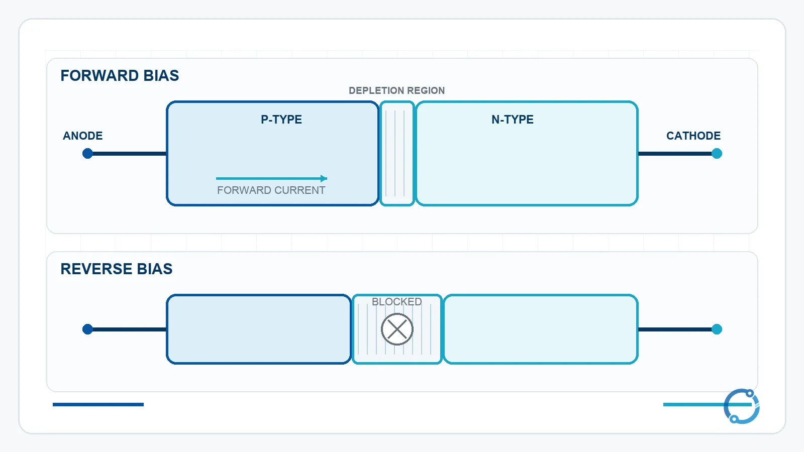
In forward bias, the anode is positive relative to the cathode and the PN junction permits current. In reverse bias, the anode is negative relative to the cathode and the junction blocks current until reverse breakdown occurs.
For a silicon PN-junction diode, a common teaching approximation is a forward drop of about 0.6 V to 0.7 V. A Schottky diode is often modeled with a lower typical drop, roughly 0.3 V, but both values depend on current and temperature. The diode symbol points in the direction of conventional current, from anode to cathode.
The symbol and the two terminals
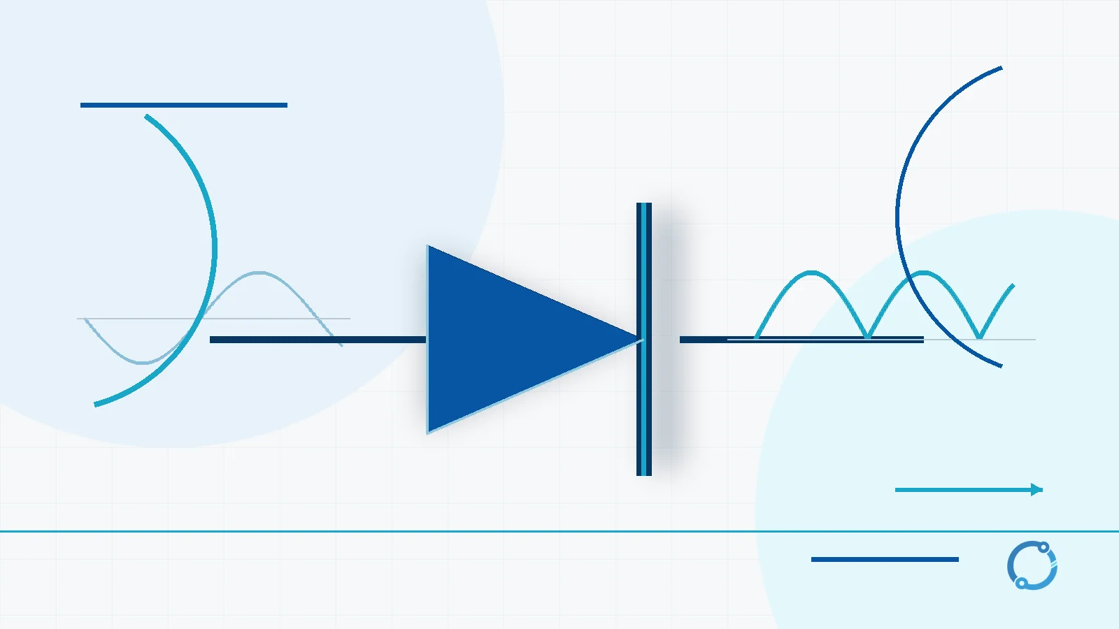
The schematic symbol is a triangle that points toward a vertical line. The triangle’s flat side is the anode and the line is the cathode. The arrow does not mean that electrons travel in that direction; it follows conventional current, the same convention used in circuit analysis.
The physical package often adds a stripe, band or molded mark at the cathode end. The exact marking is package-specific, so the symbol, part datasheet and circuit orientation are more reliable than a color alone.
The terms anode and cathode are fixed terminal names for a diode. They do not reverse when a circuit charges and discharges the way the electrochemical labels can in a battery. The battery working-principle guide explains that different naming context; a diode’s anode remains the terminal from which conventional current enters during forward conduction.
How the PN junction creates one-way behavior
A PN-junction diode is formed where p-type and n-type semiconductor regions meet. The p-type region has an excess of positive holes available for conduction, while the n-type region has an excess of electrons. The terminology describes the material’s majority carriers; it does not mean the entire p-type block is positively charged or that the n-type block is a battery terminal.
At the boundary, electrons and holes recombine and leave a region with fewer mobile carriers. This is the depletion region, also called the space-charge region. The resulting internal electric field creates a barrier.
When the anode is made positive, the applied field opposes part of that barrier. The depletion region becomes narrower and carriers can cross the junction, so forward current can rise. When the anode is made negative, the applied field reinforces the barrier. The depletion region widens and the reverse current remains very small in an ideal model.
This explanation stops at the level needed to understand the component. Real diode current depends on carrier concentration, junction geometry, temperature and the applied voltage in a nonlinear way. Those details belong in a semiconductor-physics or device-model treatment, not in the basic symbol and rectifier explanation.
Forward voltage is a real operating drop
The forward voltage, often written VF, is the voltage across a conducting diode. It is not a fixed number stamped into every silicon diode. The familiar 0.6 V to 0.7 V figure is a teaching approximation for a silicon PN junction at ordinary currents. A small-signal diode at low current may show a different value, and a power diode at high current may show a larger one.
A Schottky diode uses a metal-semiconductor junction and is often represented by a lower forward drop, with roughly 0.3 V as a typical textbook value. Schottky construction also changes switching behavior, which is why it appears in low-voltage or fast-switching applications.
The distinction matters because the diode dissipates power while it conducts:
P = VF x IF
If a diode carries 1 A with a 0.7 V forward drop, the semiconductor loss is about:
about 0.7 W
The current and voltage in that equation must both come from the same operating point. A typical value copied from a textbook is not a substitute for the manufacturer’s forward-voltage curve. A small diode carrying a tiny current may dissipate little power, while a high-current rectifier can require thermal design even though its voltage drop seems small.
This is also why circuit designers treat a diode drop differently at different voltage levels. In a low-voltage signal path, a few tenths of a volt can change the available headroom or bias point. In a power supply with a much larger output, the same drop may be a small fraction of the total, but the resulting heat still has to leave the package. A Schottky device or an actively controlled synchronous rectifier can reduce the conduction loss in some designs, but each choice changes leakage, switching behavior, cost and control complexity. The correct comparison is made at the intended current and temperature, not from the diode category name alone.
Rectification: turning AC into pulsating DC
Rectification is the process of converting alternating current into a current with a dominant DC component. The diode does this by allowing current during one polarity of the AC wave and blocking the opposite polarity.
Half-wave rectifier
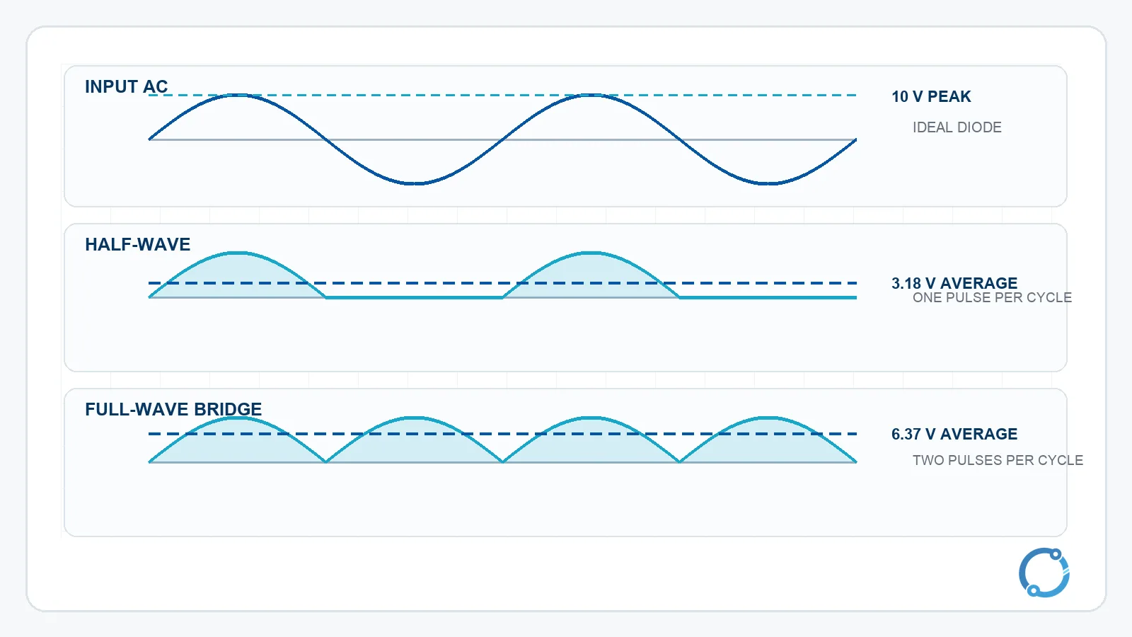
A half-wave rectifier uses one diode in series with the load. During one half of the AC cycle, the diode is forward-biased and current reaches the load. During the reverse half, the diode blocks, so the load receives an intermittent output. The result is pulsating DC, not a smooth battery-like voltage.
The AC and DC current guide explains the alternating and direct-current definitions behind this operation. The rectifier itself only changes the path available to the current; it does not create energy or remove the need for a return path.
Full-wave bridge rectifier
A bridge rectifier uses four diodes connected so that the load receives the same polarity during both halves of the AC cycle. In a typical bridge, two diodes conduct during one half-cycle and the other two conduct during the next half-cycle. The output has twice as many pulses per input cycle as a half-wave rectifier.
Full-wave rectification is common in DC supplies, battery chargers and the input stage of motor-drive equipment. A variable frequency drive uses a rectifier stage ahead of its DC bus, while an inverter performs the opposite conversion direction by reconstructing an AC output from a DC source.
The output is still pulsating. A capacitor can store energy and reduce the ripple, but the capacitor, source impedance, load and diode conduction angle all affect the result. Adding a capacitor does not make the rectifier ideal or eliminate diode voltage drop.
Worked rectifier example
Use an ideal-diode teaching model first, with a 10 V peak sine wave and no forward drop. The half-wave average over a full period is:
Vavg(half) = Vp / pi
Vavg(half) = 10 V / pi
Vavg(half) = about 3.18 V
For an ideal full-wave rectifier, both half-cycles contribute and the average is twice as large:
Vavg(full) = 2 x Vp / pi
Vavg(full) = 2 x 10 V / pi
Vavg(full) = about 6.37 V
These results assume an ideal diode with zero forward voltage. A real bridge has series voltage drops. If two diodes conduct in each half-cycle and each is approximated by a 0.7 V drop, the total conduction drop is about 1.4 V. The actual output depends on the instantaneous current, temperature and chosen diodes.
The distinction is important for low-voltage circuits. A 1.4 V drop is a small fraction of a high-voltage rectifier output, but it is a large fraction of a low-voltage supply. This is one reason a design may use a Schottky bridge, a synchronous rectifier or a different converter topology instead of assuming that every bridge behaves the same.
Reverse voltage, breakdown and the Zener boundary
When a diode is reverse-biased, the small reverse current is often treated as negligible for introductory circuit work. The device still has a reverse-voltage limit. Exceeding the rated reverse voltage can drive the junction into breakdown, which may be destructive for an ordinary rectifier but is intentional in a Zener or avalanche voltage-reference design.
The reverse voltage rating is usually discussed as peak inverse voltage, or PIV, for a rectifier. The required PIV depends on the circuit topology and the AC waveform, not only on the load’s DC voltage. This is why a diode chosen only by its average output current can be inadequate for a bridge or a circuit with inductive flyback.
Zener diodes are designed to operate in a controlled reverse-breakdown region. They are used for voltage references, clamps and some protection circuits, but they are not interchangeable with ordinary rectifiers. The design still needs attention to current limiting, tolerance, temperature behavior and the actual circuit impedance. Avalanche breakdown is another reverse-breakdown mechanism; the useful distinction here is controlled versus unintended operation, not a claim that every Zener has the same behavior.
LED: a diode that emits light
An LED is a diode whose semiconductor junction emits photons when carriers recombine under forward bias. The forward voltage depends on the material system and the emitted color. A useful teaching range is about 1.8 V to 3.3 V, but it is not a universal color-to-voltage table.
Consider a 5 V supply, an LED forward voltage of 2.0 V and a target current of 20 mA:
R = (Vs - VF) / I
R = (5 V - 2.0 V) / 0.020 A
R = 150 ohm
The resistor voltage is:
Vresistor = 5 V - 2.0 V = 3.0 V
The resistor dissipation is:
P = Vresistor x I
P = 3.0 V x 0.020 A
P = 0.06 W
The diode’s current is sensitive to the applied voltage after it begins to conduct. Connecting an LED directly across a supply without a current-limiting element is therefore a common way to overheat or destroy it. The 150 ohm result is a teaching calculation; a real design must use the actual supply, LED forward-voltage curve and intended operating current.
Main types at a glance
| Type | What defines it | Typical role |
|---|---|---|
| Rectifier diode | General-purpose PN junction optimized for power rectification | AC-to-DC conversion and reverse-voltage blocking |
| Schottky diode | Metal-semiconductor junction with a lower typical forward drop | Low-voltage rectification and fast switching |
| Zener diode | Designed for controlled reverse breakdown | Voltage reference, clamp or protection boundary |
| LED | Forward-biased junction that emits light | Indicator, illumination and optoelectronic source |
| Photodiode | Junction whose current responds to absorbed light | Light sensing and optical detection |
The table describes operating roles, not interchangeable part numbers. A diode family can have very different voltage, current and thermal ratings; those values must come from the exact device datasheet.
A photovoltaic cell is another PN-junction application, but it is optimized to convert absorbed light into useful electrical power rather than to act as a simple reverse-biased light sensor. The solar-panel working-principle guide explains that system-level energy-conversion chain.
What a diode does not do
A diode does not store a fixed output voltage like a regulated supply. It does not open and close on command like a relay or transistor, and it does not replace a fuse or miniature circuit breaker. Its forward drop and reverse limit describe one part of a circuit’s behavior, not a complete protection scheme.
It is also a mistake to treat the component as lossless. Every conducting diode converts some electrical energy into heat, and a reverse-biased diode still has leakage and a maximum voltage it can withstand. The PN junction explains the useful directionality, but the package, thermal path, current waveform and applied voltage determine whether a particular device is suitable.
The diode versus controlled devices
A diode is an uncontrolled two-terminal device. It does not have a separate control terminal that decides when it should conduct; the voltage across it and its internal physics determine the state. A thyristor or transistor introduces a control terminal and a more complex switching behavior. Those devices are separate topics and should not be inferred from the diode symbol.
The useful summary is this: the diode is the simplest semiconductor gate in the power path, but it is not a universal switch, fuse or regulator. It has a direction, a forward drop, a reverse limit and a temperature-sensitive operating curve.
Frequently asked questions
Does a diode conduct in both directions?
An ordinary diode is intended to conduct primarily in the forward direction. In reverse bias it blocks until its reverse-voltage limit is reached. Real devices have a small leakage current, and special types such as Zener diodes are designed to operate in reverse breakdown.
What is forward voltage in a diode?
Forward voltage is the voltage across a diode while it conducts in the forward direction. It is a nonlinear function of current and temperature. The common 0.6 V to 0.7 V silicon value is a teaching approximation, not a fixed value for every diode.
Why does a bridge rectifier use four diodes?
The four diodes route the load current in the same direction during both halves of the AC cycle. Two diodes conduct in one half-cycle and the other two conduct in the next, so the output has two pulses per input cycle rather than one.
Can an LED be connected directly to a supply?
No, not as a general practice. An LED needs its current limited by a resistor, a current source or an electronic driver. The diode voltage changes with current and temperature, so a direct connection can allow excessive current.
Is a Zener diode the same as a rectifier diode?
No. Both use a PN junction, but a Zener is designed for controlled reverse breakdown and is used as a reference or clamp. An ordinary rectifier is normally expected to block reverse voltage and conduct in the forward direction.