
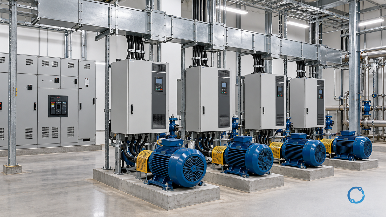
Harmonic mitigation cannot be selected from a product category alone. Define the point of common coupling (PCC) and governing limit, obtain a representative spectrum, model impedance and resonance, aggregate drives across operating cases, then specify and verify the architecture. A filter, active front end (AFE), transformer or low-harmonic drive label is not evidence of site compliance.
This method is for three-phase AC variable-frequency-drive (VFD) installations. It produces a specification and verification record, not project limits or equipment sizes.
Start with the boundary, not the filter
The first decision is where performance will be judged. The utility PCC, landlord-tenant interface, transformer secondary, department switchboard and owner-specified internal point each include different sources and loads, so each can produce a different answer.
Record the exact point and voltage; equipment inside the study; responsibility for each contribution; and the governing limit and edition.
IEEE 519-2022 describes the source-load interface as the PCC and establishes steady-state voltage and current distortion goals. It is a system boundary, not a product certificate. Its public scope notes that transients may exceed those goals.
Terminology changes with the standard. IEC 61000-2-4:2024 applies industrial compatibility levels at the in-plant point of coupling (IPC), while public-network PCC levels are addressed elsewhere. Its public scope notes that a long feeder or internal disturbance can make terminal conditions differ from the IPC. The IEC 61000-2-4:2024 page therefore supports one rule: do not move a limit between boundaries without checking the applicable standard.
The limit may come from an adopted standard, utility rule, connection agreement or owner specification. Identify the more restrictive document and whether it controls voltage, injected current, individual orders or interharmonics. Record who allocates emission capacity. IEC TR 61000-3-6:2008 illustrates the system-operator approach for medium-voltage, high-voltage and extra-high-voltage installations; its public scope says it does not address mitigation.
This prevents a common error: proving an equipment-level EMC result while saying nothing about the installation PCC. IEC 61800-3:2022 is an EMC product standard for power drive systems and machine tools. Its public scope supports equipment assessment, not a system harmonic study or utility compliance determination.
Build the representative spectrum
A total harmonic distortion reading is not a spectrum, and a nameplate does not supply one. The study needs harmonic magnitude and phase data, or a validated model that produces them.
Use measured data when the installation exists. Define the point, instrument transformers, class, interval, frequency range and phase reference. IEC 61000-4-30:2025 defines in-situ voltage and current harmonic measurement methods, including Class A and Class S. Its public scope sets method, not acceptance limits.
Separate the measurement campaign into useful states:
| State | Why it matters |
|---|---|
| Background with proposed drives off | Separates existing distortion from the new contribution |
| Minimum stable drive load | Reveals partial-load spectra and light-load control states |
| Normal production mix | Provides the design baseline, not merely a convenient snapshot |
| Maximum credible nonlinear load | Tests the highest distortion duty and thermal stress |
| Startup, transfer, bypass or regeneration | Captures states that steady-state screening may omit |
| Future expansion | Prevents a solution that fits only today’s drives |
For a new installation, calculate the spectrum from documented topology, rectifier type, pulse number, input impedance, filter or AFE arrangement and load points. Validate it against comparable tests. Equipment evidence should identify the circuit and conditions behind the spectrum; otherwise, verify it for the project.
IEC TS 63222-3:2024 describes frequency-domain modelling of user installations, typically through the 50th harmonic. Its public scope excludes network elements, so their data must come from the responsible parties. Use the VFD selection guide for the drive decision, not as a substitute for a harmonic model.
Model impedance, short-circuit ratio and resonance
Harmonic current produces harmonic voltage through network impedance. That impedance changes with source configuration, transformer impedance and tap, cables, generators, capacitors, filters, background loads and frequency.
Build cases for utility only, generator only, parallel sources, bus ties, redundant transformers and emergency operation. Include correction capacitors and existing filters, then scan the relevant orders. Resonance can amplify a harmonic even when nonlinear load is not unusually large.
The short-circuit ratio (SCR) describes source strength relative to a converter or drive group, but its meaning depends on formula and base. State the short-circuit capacity, voltage base, drive apparent-power basis and network configuration. Do not treat one SCR as a universal threshold: a high-ratio installation can still have resonance or background distortion.
Model every candidate. A passive filter changes impedance and can create resonance; an active filter changes injection and response; a phase-shifting transformer changes phase and impedance; a low-harmonic drive may leave background or higher-order components limiting. Re-run the study for each case.
IEEE 3002.8-2018 covers study need, data, problem recognition and corrective measures. Its public scope supports this iteration but supplies no universal resonance margin or acceptance value.
Aggregate the drive population correctly
The common-bus harmonic current is not the arithmetic sum of rated drive currents. Topology, pulse number, transformer phase shift, control mode and loading differ. Harmonic phasors can add or partly cancel, and the result changes with the operating combination.
Create an inventory before calculating the aggregate:
| Drive or group | Data needed |
|---|---|
| Converter topology | Diode rectifier, thyristor rectifier, AFE, active rectifier or another documented arrangement |
| Pulse number and transformer | Rectifier configuration, vector group, phase shift and input impedance |
| Rating basis | Motor shaft demand and actual input current at each operating point |
| Harmonic evidence | Spectrum with magnitude, phase and stated test conditions |
| Operating envelope | Speed, torque, load, bypass, sleep and regeneration states |
| Group behaviour | Which drives run together, diversity, redundancy and future additions |
The cancellation question is whether harmonic currents have the required phase relationship, not whether drives share a kW rating. Phase-shifting transformers can support cancellation, subject to pulse numbers, vector groups, load balance and control; the connection alone proves no percentage. Use the motor and VFD sizing guide for machine duty; harmonic aggregation is separate.
Calculate all-on, typical, minimum, degraded and future cases. Fewer drives can be worse if they approach resonance or change the dominant phase relationship. Include standby drives with a different configuration. For four-wire systems, assess neutral duty with the neutral harmonic sizing guide.
Tie the solution to the load cycle
The load cycle determines which spectrum is present, how long a filter carries current and how an active device must respond. Light-load operation can have a different signature. Frequent starts, reversing, regeneration, bypass and long dwells create states that a peak-load study misses.
Define time at each speed and torque, repetitions, minimum load and maximum demand, then map each state to a harmonic case. A device that cannot follow the actual cycle is incomplete.
This also sets the evidence: passive-filter current and thermal duty; active-filter range and response; AFE spectra at relevant conditions; transformer vector group, impedance and sharing.
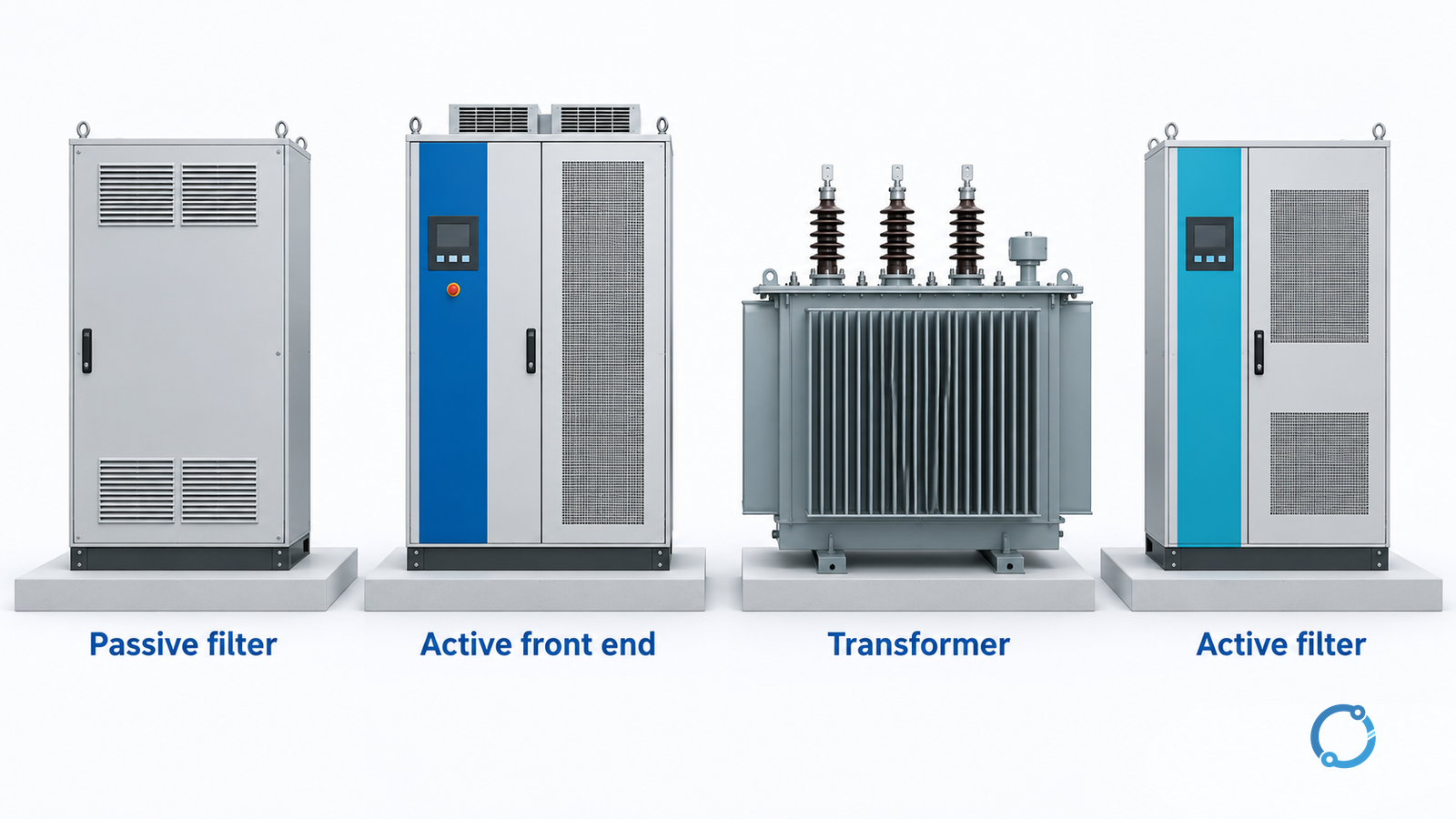
Compare mitigation architectures conditionally
This comparison identifies candidate conditions and disqualifying evidence. It does not rank products or establish compliance.
| Architecture | Strong candidate when | Main limitation or study question | Evidence before specification |
|---|---|---|---|
| Passive or tuned shunt filter | Target orders are stable and the study shows suitable duty | Impedance changes, background interaction and effectiveness can shift with the network | Tuning, current and voltage duty, resonance, protection, losses and temperature |
| AFE or low-harmonic drive | New drives can be selected as a system with documented line-side spectra | A cleaner input does not remove other loads or background distortion | Spectrum over the load range, supply conditions, EMC, motor interface and faults |
| Isolation or phase-shifting transformer | Drive groups and connections support cancellation, or the transformer has another documented function | Isolation is not filtering; cancellation depends on vector group, pulse number, balance and control | Vector group, phase shift, impedance, load pairing, modelled cases and losses |
| Active harmonic filter | Multiple orders or a changing spectrum need controlled compensation | Location, sensing, bandwidth, capacity, response, stability and source interaction need design | Site spectrum, load cycle, control, protection, losses and failure modes |
| Hybrid arrangement | No single architecture meets spectrum, resonance and range needs | Added interfaces create failure modes and shared responsibility | Combined model, equipment coordination, staged commissioning and acceptance |
The passive-filter row is not permission to order a generic tuned bank. IEEE 1531-2020 covers passive shunt-filter application and specification across LV, MV and HV; its public scope makes filtering an application-engineering subject.
An AFE or low-harmonic drive changes only its line-side behaviour. IEC 61800-2:2021 describes an adjustable-speed AC drive as a system with conversion, control, protection, monitoring and a motor; its public scope supports evaluating the complete system. Because supply, other drives and cabling remain, an equipment test is not a site result.
Do not confuse harmonic mitigation with power-factor correction
An automatic power-factor-correction (APFC) bank is not a universal harmonic filter. Capacitors interact with inductance and may worsen resonance. The power-factor guide explains compensation; the capacitor-bank guide explains power and control paths. Neither is a harmonic-mitigation method.
When correction and mitigation are combined, specify reactive target, harmonic duty, resonance and switching together. The APFC MCCB checklist is protection, not a filter study.
Input-to-specification decision matrix
Use this matrix to turn evidence into a shortlist. The final column is a hold point, not permission to buy.
| Site condition | Shortlist candidates | Do not assume | Specification evidence required |
|---|---|---|---|
| Stable problem with adequate spectral data | Passive filter, low-harmonic drive or AFE | A tuned filter is safe because it targets the dominant order | Tuning, duty, resonance, protection, thermal design and post-installation spectrum |
| Several drives in balanced groups with suitable transformers | Phase-shifting groups, low-harmonic drives, passive or hybrid | Vector groups alone guarantee cancellation | Phase-angle study, load pairing, impedance and common-bus spectrum |
| Changing load, multiple orders or a dynamic process | Active filter, AFE/low-harmonic drive or hybrid | An active filter corrects every frequency everywhere | Control boundary, response, bandwidth, capacity, losses and failure behaviour |
| Material background distortion from other loads | System filter or active solution after separation | Replacing one drive fixes the whole PCC | Background spectrum, contribution allocation, network model and source cases |
| Resonance or capacitor interaction | Re-run the study before accepting a candidate | A detuned reactor or larger filter is automatically the answer | Impedance scan, capacitor/filter interaction, protection and switching |
| Likely future expansion | Architecture with documented headroom and re-study points | Today’s duty is the design maximum | Future drive schedule, cases, spare capacity and update trigger |
| Incomplete or inconsistent evidence | Hold and collect data | A datasheet closes the gap | Measurement plan, model validation, test conditions and qualified review |
Each candidate needs a reason to remain, a disqualifying condition and evidence that will settle the choice.
Specify, verify and hand over
The specification should define the study boundary, governing limit, spectrum basis, network cases, drive aggregation, load cycle and commissioning evidence.
Require a single-line diagram; governing limit and edition; spectra with phase and state metadata; model, assumptions, sensitivity cases and resonance scan; short-circuit basis and SCR formula; candidate topology, filter, vector group and control; test conditions and spectra; losses, cooling, protection and failure review; and commissioning tied to the approved model.
After installation, measure at the agreed boundary across normal, minimum, maximum and transition states. Compare spectra, not one aggregate indicator. Confirm control range and the absence of unexpected resonance. Require re-study when drives, sources or load cycle change.
Surveys, current-transformer work, filter installation, capacitor discharge and commissioning expose personnel to hazardous energy. Qualified persons must follow approved isolation, verification, PPE and local procedures; a plan is not permission to work energized.
The correct selection is a traceable argument: known boundary, representative spectrum, modelled network and drives, covered load cycle, fair comparison and verification at the PCC. If a link is missing, the answer is a hold, not a product category.