
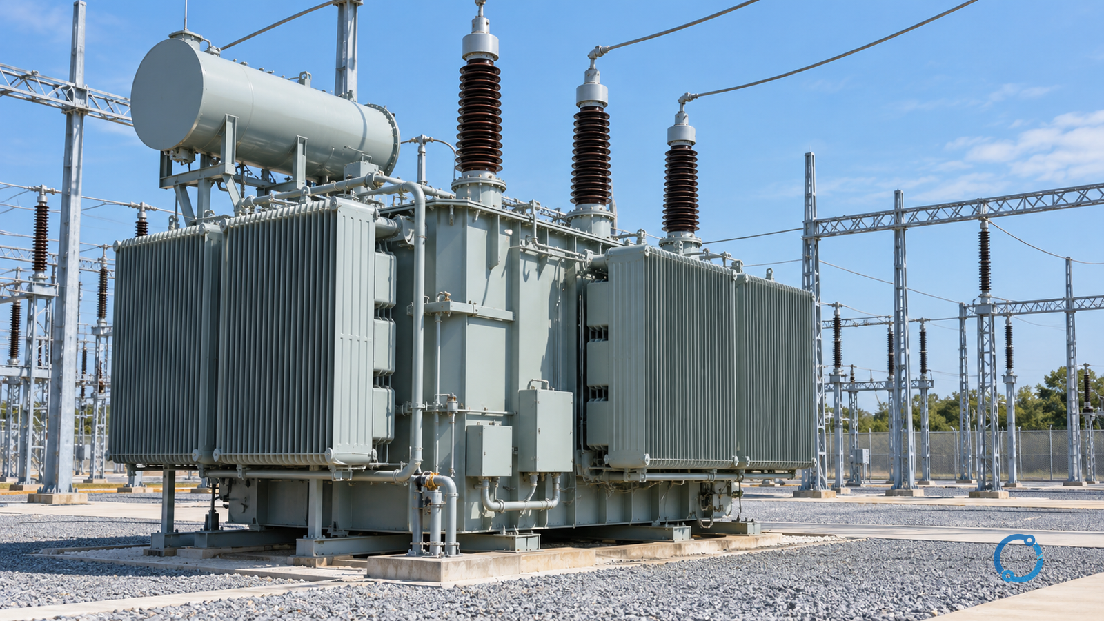
A shunt reactor is connected across an AC power system to absorb inductive reactive power. It can help control voltage when a lightly loaded transmission line, cable, or network produces more capacitive reactive power than nearby equipment absorbs. Its effect depends on the actual network, the connection point and the voltage at its terminals; a reactor is not a substitute for a system voltage study.
For a substation engineer, the useful question is not simply “How many MVAr?” It is: which operating conditions need absorption, where must it remain connected, and can the complete switching and protection arrangement handle those conditions? The answers tie together steady-state voltage control, transient duty, fault detection and operating procedures.
This article explains those relationships for high-voltage AC systems. It does not specify relay settings, switching sequences, clearances or a final reactor rating. Qualified engineers and system operators must use the approved studies, equipment information and local procedures for an actual installation.
Why a network needs reactive-power absorption
Transmission lines and cables have shunt capacitance as well as series impedance. When the system is lightly loaded, the capacitive component can make a significant contribution to the local reactive-power balance. Voltage may rise, particularly when the available network is weak or the line is long. The magnitude and location of the rise depend on the system topology, voltage-control resources, load and operating state.
A shunt reactor provides an inductive path in parallel with the network. In normal operation it absorbs reactive power. By changing the balance at its connection point, it can help reduce an overvoltage tendency. The U.S. Department of Energy describes a shunt reactor as equipment used to absorb reactive power and lower system voltage. In the DOE’s National Transmission Planning Study, voltage and reactive-power planning are assessed across network operating conditions; a single nominal operating point is not the whole planning problem.
The effect is not guaranteed to be the same at every bus. A reactor affects its immediate electrical surroundings most directly, while the rest of the system responds through the network impedance and other controls. Adding too much fixed absorption can create an undesirable low-voltage condition in another state. A study therefore evaluates both the case that needs the reactor and cases in which the same reactor may be unnecessary or unavailable.
Do not confuse a shunt reactor with a series reactor. The former is a parallel branch used here for reactive-power absorption; the latter is inserted in a current path for a different purpose, such as limiting current. The IEC 60076-6 catalogue scope covers several reactor types. That breadth does not make their duties interchangeable or certify any individual product.
How connection location changes the operating question
A reactor may be connected to a substation bus, associated with a transmission line, or connected through another suitable voltage level or arrangement. Actual substations use different breakers, disconnectors, protection zones and switching schemes. The useful distinction is which part of the network remains connected when a line or bus changes state.
| Connection concept | Primary operating question | Study and protection implication |
|---|---|---|
| Bus-connected | Is absorption needed at this bus independently of a particular line? | Evaluate bus operating states, other voltage controls and the reactor branch’s own switching and protection boundaries. |
| Line-associated | Should absorption follow a particular line or cable as its connection changes? | Check what remains energized for each line-breaker state, including remote-end supply and the treatment of line and reactor faults. |
| Connected at another voltage level | Is a lower-voltage connection electrically effective in the relevant network states? | Include intervening transformer impedance, reactive flows, losses, tap position and the capability of the selected bus. |
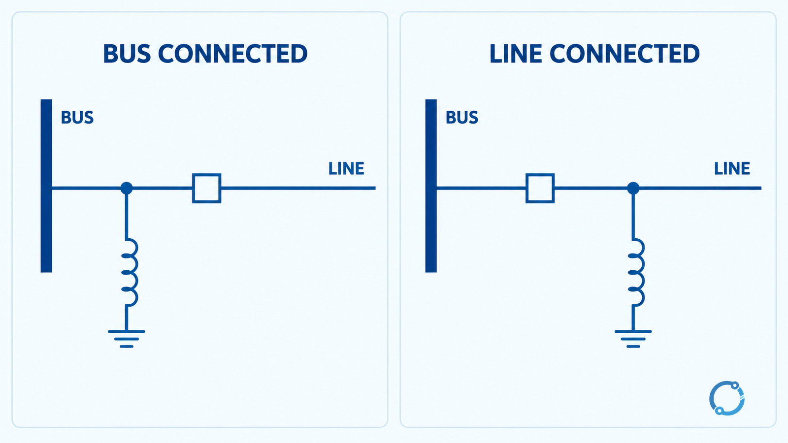
In a bus-connected concept, a reactor may remain connected to the bus after a particular line is opened, subject to its own branch arrangement. In a line-associated concept, the reactor’s state depends on its connection and on all sources that can energize that line. Opening one local breaker does not, by itself, prove that the line or reactor is deenergized: a remote terminal, coupling or another source may still matter.
The diagram is deliberately simplified. It does not establish that a reactor has a dedicated breaker, that every line-connected reactor operates with the line, or that an open device provides a safe work clearance. For a broader orientation to substations, see distribution substation equipment and layout; a transmission scheme can have substantially different equipment and protection requirements.
Voltage changes the absorption of a fixed reactor
For an ideal, balanced three-phase reactor represented by a fixed reactance at a fixed frequency, reactive-power absorption varies approximately with the square of its terminal voltage:
Q / Qrated ≈ (V / Vrated)²
Here, Q is the magnitude of inductive reactive power absorbed, and V is the voltage on the same consistent basis as the rated voltage. The expression follows from the ideal relationship between voltage, reactance and reactive power. It is a useful first check, not a substitute for the manufacturer’s characteristics or a load-flow model.
For example, if a simplified fixed reactor absorbs 100 MVAr at its rated voltage, the ideal estimate at 0.95 per unit voltage is:
100 × 0.95² = 90.25 MVAr
At 1.05 per unit, the corresponding estimate is 100 × 1.05² = 110.25 MVAr. These are arithmetic illustrations, not permissible operating points. Actual behavior can differ because of magnetic nonlinearity, tolerances, frequency, temperature, tap or control position, and operating restrictions. Equipment limits and the network study decide whether a condition is acceptable.
This voltage dependence matters because the reactor provides more absorption as voltage rises in the ideal model, but less when voltage falls. A device selected only from its nominal MVAr label can therefore be misrepresented in an abnormal operating case. Variable reactors and switched banks add further control and equipment constraints; their exact response cannot be inferred from this simple formula.
Fixed, switched and variable absorption
A fixed reactor supplies its characteristic absorption whenever it is energized. This can be appropriate when the need is persistent, but its continued connection in low-voltage or heavily loaded conditions must be checked. A fixed connection is an operating choice, not proof that no breaker, protection, isolation or maintenance arrangement is needed.
A switched reactor can be brought into or out of service as the system state changes, subject to its approved switching scheme. It gives the operator another discrete control action, but every operation has equipment duty and control consequences. The study needs to consider the requested operating frequency, switching transients, alarm and trip behavior, and what happens if a command or indication fails.
A variable reactor can change its effective absorption within its equipment-specific range. The range, response, control mode and availability come from the actual design. It should not be assumed to respond like a power-electronic compensator, nor should a general article assign a universal speed or control interval.
These options can coexist with other resources, including generator excitation, transformer taps, capacitors and dynamic compensation. Their coordination is a system-control question: an individual controller’s local voltage objective may conflict with a neighboring controller or exceed another device’s capability if the operating strategy is not coordinated.
Why reactor switching needs its own assessment
An inductive branch presents a switching duty different from a capacitive bank or an ordinary load. When an inductive current is interrupted, the interaction between the switching device and the surrounding circuit can produce transient voltages. The outcome depends on the interrupter, current, circuit capacitances, reactor characteristics, connections and insulation. Energization also needs a project-specific assessment; do not assume that a breaker selected for a general current rating automatically covers every transient duty.
One relevant mechanism is current chopping: an interrupter can cease current before its natural current zero. The energy and circuit response may then contribute to overvoltage. The current-chopping explainer discusses that mechanism; it does not establish a safe switching duty for an individual reactor. The CIGRE overview of shunt capacitor switching explicitly distinguishes the requirements of devices switching reactors from those switching capacitors. Capacitor-bank test figures should not be transferred to a reactor breaker.
A switching-duty review normally assembles, at minimum:
- the reactor’s rated voltage, frequency, reactive power and applicable operating range;
- actual breaker technology, ratings, switching history and intended operation count;
- the physical arrangement, including connecting leads, adjacent equipment and credible source configurations;
- the insulation withstand of the equipment exposed to the transient;
- any proposed surge arresters or controlled-switching measures and their documented application limits;
- study cases covering energization, deenergization and credible abnormal states.
The outcome might require a detailed electromagnetic-transient study, manufacturer evidence, changes to the arrangement or additional protective measures. A surge arrester is selected and coordinated for the specific duty; its presence alone does not prove that all equipment insulation is protected. For the distinction between arrester capability, placement and insulation coordination, see surge arrester selection for transformer protection. The same coordination discipline applies, although reactor-specific duties must be assessed separately.
Protection: define the zone before choosing functions
The protection arrangement starts with a defined zone: which terminals, bushings, connections and switching devices must be covered, and which current and voltage measurements are available? The answer changes with the reactor construction, connection and system grounding. A protection diagram should also show what each protective function trips, what is alarm-only, and how backup protection operates if the primary clearing path is unavailable.
| Protection question | Evidence to assemble | Why it matters |
|---|---|---|
| What is inside the protected zone? | Single-line diagram, current-transformer locations and breaker trip paths | A boundary error can leave a connection uncovered or cause an inappropriate trip. |
| What internal or earth faults must be detected? | Reactor design, grounding arrangement and calculated fault cases | Fault current and available measurement signals depend on the actual circuit. |
| How is normal energization distinguished from a fault? | Reactor behavior, switching studies and relay application information | Normal transients and abnormal events must not be treated as identical without supporting evidence. |
| What happens if a breaker or DC supply fails? | Trip-circuit design, backup clearing, auxiliary supply and alarms | A relay decision is useful only if the associated clearing path is dependable. |
| What non-electrical indications are provided? | Manufacturer’s protection and alarm interface for the actual reactor | Thermal, liquid or other device indications depend on construction; not every reactor has the same sensors. |
Depending on the design, protection may include differential, overcurrent, earth-fault, thermal or other functions. This list is not a mandatory scheme: the engineer must establish sensitivity, security, speed, measurement quality and coordination from the actual installation. The transformer differential relay settings guide illustrates a separate calculation workflow; transformer settings and examples do not automatically apply to reactors.
Current-transformer ratio, polarity, accuracy and saturation behavior deserve attention because the relay sees secondary quantities, not the primary circuit directly. The trip output and its DC supply also belong in the design review. Substation trip-circuit verification provides a separate checklist for those interfaces.
Build the study cases around actual system states
A practical review connects each scenario to a decision, rather than running only a nominal power flow. At minimum, the system owner should decide which of the following apply and document the result:
- Light load and high voltage: identify where voltage exceeds an approved limit and whether the proposed reactor changes the relevant bus conditions sufficiently.
- High load or low voltage: determine whether fixed absorption worsens the condition and whether operating controls can remove it when permitted.
- Line or equipment outage: assess the remaining sources, reactive resources and the reactor’s actual connection after the outage.
- Energization and restoration: assess the approved system sequence and equipment limits, including the available reactive-power resources and potential transient conditions.
- Protection or breaker failure: identify the backup clearing path, resulting system exposure and operator indication.
- Maintenance state: identify isolation points, alternative supplies, grounding provisions, work boundaries and any loss of system voltage-control capability.
For each case record the network model and revision, starting topology, voltage and load assumptions, reactor state, relevant limits, result, owner and action. The same diagram should not silently stand in for all breaker positions. If a line can be supplied remotely, show that source explicitly in the actual study model.
Operating and safety boundary
High-voltage equipment can remain hazardous through remote supply, induced voltage, stored energy or an incorrect indication. A simplified single-line drawing and a relay status display are not a work permit. Work and switching must follow the system operator’s approved instructions, the site’s isolation and grounding plan, the equipment documentation and applicable local rules. Qualified personnel must establish and verify the safe work condition using the prescribed process.
In the United States, OSHA 29 CFR 1910.269 addresses covered electric power generation, transmission and distribution work, including deenergizing and protective grounding provisions within its scope. Other jurisdictions and installation types may apply different requirements. This overview does not replace those rules or authorize energized work.
The handover decision is complete when the system study, switching duty, insulation coordination, protection and operational procedures describe the same physical connection and operating cases. If any one is based on a different topology or undocumented assumption, resolve that mismatch before treating the arrangement as ready for service.
Sources
- U.S. Department of Energy: I-5 Corridor Reinforcement Project environmental impact statement, description of shunt-reactor function.
- U.S. Department of Energy: National Transmission Planning Study, Chapter 4, AC power flow and reactive-power planning.
- IEC 60076-6:2007, Power transformers — Part 6: Reactors, official scope.
- CIGRE: Shunt capacitor switching in distribution and transmission systems, overview distinguishing switching duties.
- OSHA 29 CFR 1910.269: Electric power generation, transmission, and distribution, U.S. regulatory scope and work controls.