
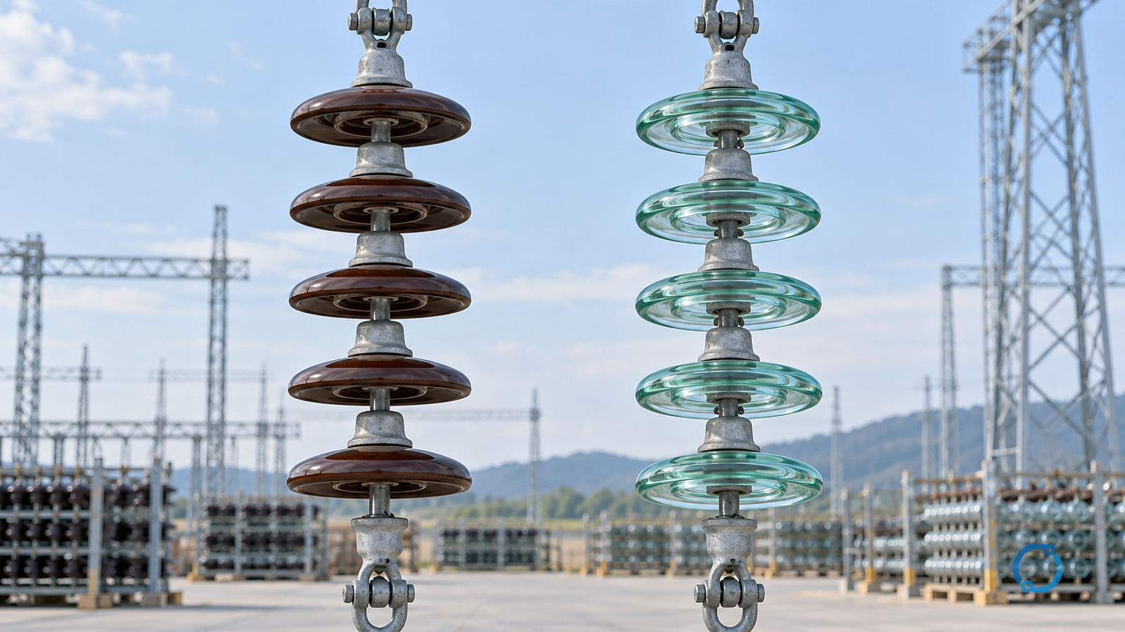
Porcelain and glass both have long service histories in overhead-line insulation. They are both ceramic or glass dielectric materials, both can be formed into cap-and-pin and other insulator types, and both can perform acceptably when the complete insulator, hardware and line design are correct.
The useful comparison is not “Which material is better?” It is “Which material and insulator construction provide the required electrical and mechanical duty with an inspection and replacement strategy the asset owner can operate?”
IEC 60383-1 covers insulator units for overhead lines with a nominal voltage greater than 1 kV, including ceramic or glass units. IEC 60383-2 covers test methods and acceptance criteria for insulator strings and sets. Those standards establish a framework for design and qualification evidence; they do not turn a material name into a universal reliability rating.
Porcelain and glass differ in the way some failures become visible. That difference matters for inspection and outage planning. It does not remove the need to verify pollution performance, mechanical load, hardware compatibility, electrical ratings and the limits of visual inspection.
Start with the complete insulator, not the material
An overhead-line insulator is a system of parts:
- the insulating body;
- the cap and pin or other hardware;
- the cement or coupling interface;
- the sheds and creepage path;
- the line and support attachments;
- the protective coatings where applicable;
- the string or set arrangement;
- the associated arcing and grading hardware.
Material selection alone cannot decide the product. A porcelain unit and a glass unit with similar dimensions can have different shed profiles, cementing, hardware, mechanical ratings and test evidence.
Record the following before comparing:
- nominal system voltage and insulation level;
- AC or DC duty;
- mechanical load and cantilever requirements;
- creepage and pollution environment;
- string or set configuration;
- conductor and hardware interfaces;
- altitude, temperature and seismic conditions;
- inspection and replacement policy;
- applicable standards and project tests;
- expected service life and spares strategy.
If the insulator is intended for an unusual environment, the comparison may be dominated by pollution, ice, sand, vibration or vandalism rather than the base material.
How porcelain insulators are made and what that implies
Porcelain insulation is formed from ceramic materials and fired at high temperature. The fired body is hard, electrically insulating and dimensionally stable. The line insulator is assembled with metal hardware, commonly through cemented or mechanically coupled interfaces.
Porcelain is used for cap-and-pin suspension insulators, post insulators, bushings and other apparatus insulation. The material can be shaped into complex shed profiles and can be glazed to manage surface contamination and moisture.
Mechanical behaviour
The porcelain body carries mechanical and electrical duty. It is brittle, so a mechanical defect can propagate into fracture. The metal cap, pin and cement interfaces must transfer the load without introducing concentrated stress or corrosion.
Inspection can reveal:
- chips and cracks;
- glaze damage;
- cement or cap movement;
- corrosion products;
- flashover tracks or burns;
- surface contamination;
- missing or damaged arcing hardware.
A visible crack is important, but the absence of a visible crack does not prove the insulator is sound. Internal or interface defects may need electrical, mechanical or laboratory evidence depending on the inspection regime.
Environmental behaviour
A porcelain surface can retain contamination and moisture. Rain washing, shed geometry, glaze condition and pollution severity affect the withstand performance. A design for a clean rural site cannot be copied into salt or industrial pollution without checking the equivalent creepage, shed profile and washing or coating strategy.
How glass insulators are made and what that implies
Toughened glass is heat-treated to create compressive stress in the surface and tensile stress inside. When some forms of mechanical or thermal damage exceed the intended stress pattern, the unit can break into many small fragments rather than remain as one cracked body.
That property can make a broken unit conspicuous. It does not mean that every glass defect is visible from the ground, that a glass unit cannot lose electrical performance while remaining intact, or that cracking is a reliable substitute for inspection.
Mechanical behaviour
The toughening process and the cap-pin assembly define the strength and failure mode. Impact, hardware mismatch, thermal shock, manufacturing defects, mechanical overload and installation damage can still cause failure. The unit must be qualified for the intended mechanical duty, not selected from a generic material comparison.
Inspection can reveal:
- missing discs or fragments;
- intact but displaced fragments;
- chipped edges or puncture paths;
- corrosion at the cap or pin;
- flashover marks;
- contamination;
- damaged or missing grading hardware.
A broken glass unit may remain partly in position with some fragments attached. That can preserve a visual trace but does not mean the insulator string still has its designed electrical or mechanical performance.
Environmental behaviour
Glass insulators also need correct creepage, shed design and surface maintenance. Toughened glass is not automatically pollution-proof. Salt, cement dust, agricultural chemicals and industrial deposits can form a conductive layer and erode the insulation margin.
Symmetric comparison matrix
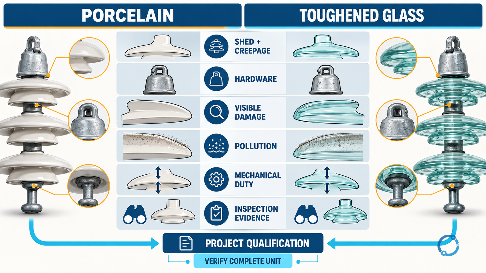
| Dimension | Porcelain | Toughened glass | What must be verified |
|---|---|---|---|
| Insulating body | Fired ceramic body, often glazed | Toughened glass body | Material specification and manufacturing evidence |
| Visible breakage | Cracks, chips or fracture may be visible, but not every defect is external | Mechanical damage may create prominent fragmentation | Inspection method and defect criteria |
| Hidden defect | Internal or interface defects can be difficult to see | Some defects can remain difficult to classify | Additional tests where required |
| Hardware | Cap, pin and cement interface must be qualified | Cap and pin arrangement must be qualified | Complete-unit type test and interface review |
| Mechanical duty | Brittle body; inspect for cracks and load-path damage | Toughened body; inspect for fragmentation and load-path damage | Rated load, string arrangement and hardware |
| Pollution | Shed, creepage and glaze condition matter | Shed, creepage and surface condition matter | Site pollution and maintenance plan |
| Repair | Replacement of damaged unit or set | Replacement of damaged unit or set | Outage and spares strategy |
| Decision evidence | Product, test, application and inspection data | Product, test, application and inspection data | No material score can replace the evidence |
This matrix deliberately avoids a “winner” column. It asks each material to answer the same project questions.
Failure modes: what may happen and what it means
Mechanical fracture
Porcelain may crack or fracture; glass may fragment. In both cases, the load path through the string changes. Adjacent units can be overloaded, hardware can move, and the electrical clearance or voltage distribution may change.
A broken unit is not simply a cosmetic defect. The inspection response should identify the string, isolate or replace as required, inspect adjacent units and hardware, and determine whether the cause was impact, installation, corrosion, vibration or another mechanical mechanism.
Puncture or electrical damage
A flashover can leave tracks, burns or surface damage. Electrical puncture may occur within the body, at an interface or through a region not easily visible. Visible burn marks should trigger a check of the complete string and the line’s protection record.
The material label does not determine whether a puncture is possible. The voltage distribution, wave shape, pollution, moisture, hardware and product design all affect the dielectric duty.
Surface contamination
Pollution is a system-level problem. The shed profile must be suitable, the creepage path must remain effective, and the maintenance policy must match the site. A porcelain glaze or a glass surface may resist wetting differently, but neither removes the need to inspect contamination and washing effectiveness.
Hardware corrosion
Cap, pin, cotter, yoke and clamp materials can corrode. Corrosion products may change the load path or introduce a conductive path. Inspect the hardware as part of the insulator, not as an unrelated accessory.
Thermal and environmental ageing
Temperature cycling, UV exposure, moisture and chemical contamination can affect glazes, coatings and interfaces. Service records should record the environment and any observed deterioration, rather than assuming that a material has a fixed lifetime.
Inspection is not a material contest
The inspection plan should state what the inspector is expected to detect and what action follows.
Ground-level visual inspection
This may identify:
- a missing glass disc;
- a hanging or broken porcelain unit;
- visible flashover damage;
- displaced hardware;
- abnormal contamination;
- vegetation or foreign objects.
It can miss:
- internal defects;
- small cracks;
- moisture ingress;
- hidden cement deterioration;
- defects on the far side of a unit;
- a partially failed string that still maintains mechanical continuity.
Close or detailed inspection
Accessible units can be examined for chips, cracks, glaze damage, fragmentation, corrosion and hardware condition. Binoculars, cameras, drones, ropes or platforms can change the observation geometry, but each method has limitations. Image quality and distance must be sufficient to identify the defect rather than merely create a picture.
Electrical or mechanical testing
Testing may be appropriate for a batch, sample, unusual defect or post-fault investigation. The test object and method must match the question. A routine production test, type test and field diagnostic are not interchangeable.
Action criteria
The inspection plan should define:
- which defects require immediate isolation;
- which require a temporary restriction or increased monitoring;
- which can remain in service pending the next planned outage;
- how loads and adjacent units are assessed;
- who has authority to close the finding.
Without action criteria, “inspect the line” is not a usable maintenance instruction.
Pollution and creepage deserve their own calculation
Do not select a shed profile from a short material description. The project must determine:
- pollution type and severity;
- wetting and drying cycles;
- wind direction and nearby sources;
- creepage requirement;
- shed geometry and protected creepage;
- altitude and air density;
- maintenance and washing access;
- coating or hydrophobic surface where justified.
Porcelain and glass can both be designed for polluted environments, but the shed design and the maintenance strategy must support the claim. A longer creepage number is not useful if the shed geometry allows bridging or if the surface is never cleaned.
Mechanical design needs the complete string
The insulator’s mechanical rating alone is not enough. Consider:
- conductor tension and sag;
- wind and ice loading;
- galloping or vibration;
- short-circuit electromagnetic force;
- hardware misalignment;
- tower movement;
- string configuration;
- installation method;
- dead-end versus suspension duty.
The material response to a failed unit differs, but the line must still tolerate the specified loads. Use the project’s design criteria and the complete-unit test evidence. Do not compare a single material property against a full assembly requirement.
Type tests do not transfer automatically to every line
A type test describes the tested design under stated conditions. It does not prove that a differently rated unit, modified hardware, longer string or more polluted project site will perform the same way. Before reusing a family’s test evidence, confirm that the insulator body, cap and pin design, coupling length, mechanical rating, shed profile and relevant test arrangement are within the qualified scope.
The same logic applies to supplier substitutions. A certificate with the same standard number is not enough if the offered unit is a different design. Record the exact catalogue identity, drawing revision and test report. Confirm that the hardware and conductor fittings match the tested or approved interfaces.
Acceptance evidence and field inspection also answer different questions. A delivery inspection can reveal transport damage, but it cannot reproduce a type test. A post-fault inspection can find visible damage, but it cannot by itself prove that an apparently intact string retains its rated mechanical or electrical performance.
Storage and installation can create defects
Insulators are often treated as robust because they are made for outdoor service. That does not make installation handling irrelevant. Mechanical impact, dropped units, over-tensioned fittings, mismatched cotter pins, incorrect packing and contamination during storage can all reduce the evidence available at commissioning.
Keep the delivery records, inspect for chips or fragmentation, verify hardware identity and follow the approved lifting and installation method. Do not install a visibly damaged unit because one material is expected to provide a visible warning while the other is not. Any material can be damaged before it reaches the tower.
Project qualification checklist
Before selecting a family, complete this checklist:
System duty
- rated voltage and insulation level;
- AC/DC and transient considerations;
- required creepage and pollution class;
- electrical test basis.
Mechanical duty
- rated mechanical load;
- string and hardware arrangement;
- wind, ice, vibration and short-circuit load;
- tower rotation and conductor tension.
Environmental duty
- pollution source and severity;
- moisture and condensation;
- salt and chemical exposure;
- UV, temperature and altitude;
- inspection access.
Asset-management duty
- inspection frequency and method;
- defect criteria;
- spare-unit strategy;
- replacement tools and outage plan;
- training and reporting.
Commercial and evidence duty
- complete-unit data;
- type test and routine test records;
- traceability of hardware;
- installation instructions;
- delivery inspection;
- lifecycle cost and replacement assumptions.
The result is a project-specific selection, not a universal statement that glass or porcelain wins.
Worked decision case
Consider a coastal line with high salt deposition, limited outage windows and difficult ground access. Two materials are proposed with the same nominal voltage and mechanical rating:
- porcelain units with a specified shed profile and glaze;
- toughened-glass units with a comparable creepage design.
The material difference may affect how mechanical damage appears and how inspectors record it. But neither proposal can be approved until:
- the pollution duty is matched to the shed and creepage design;
- the cap-pin hardware and cement interface have suitable evidence;
- the string passes the required mechanical and electrical qualification;
- the inspection method can see the relevant defect at the available access;
- the replacement and spares plan can respond to the expected failure mode;
- the project accepts the maintenance and outage consequences.
If one proposal has better packaging and inspection visibility but weaker evidence for the coastal environment, it should not win simply because the failure mode is easier to see.
Common claims to reject
Several claims appear frequently but are too broad:
- “Glass always breaks and porcelain always cracks.”
- “Glass gives early warning, so it never fails without notice.”
- “Porcelain damage is always hidden.”
- “A longer creepage design is adequate in every polluted site.”
- “Type-tested insulators are approved for every line.”
- “The material alone determines service life.”
- “A visual inspection can prove that a string is electrically sound.”
Each statement converts a tendency or a limited test into a universal rule. Use them only as questions for inspection and evidence collection.
Final selection rule
Select porcelain or glass by passing the same project gates:
- electrical duty;
- mechanical duty;
- pollution and environment;
- hardware and complete-unit interface;
- failure visibility and inspection capability;
- testing and traceability;
- maintenance, spares and lifecycle plan.
The material choice should follow evidence about the complete insulator and the operating system. A well-designed porcelain string and a well-designed glass string can both be appropriate; a material reputation cannot compensate for a mismatched shed, weak hardware, unsupported test claim or inadequate inspection plan.
For adjacent insulation topics, read insulation resistance testing, medium-voltage cable insulation types, MV cable termination stress control and creepage failures and insulation for busbars.
Sources
- IEC, IEC 60383-1:2023 Insulators for overhead lines with a nominal voltage above 1,000 V – Part 1: Ceramic or glass insulator units for AC systems – Definitions, test methods and acceptance criteria.
- IEC, IEC 60383-2:1993 Insulators for overhead lines with a nominal voltage above 1,000 V – Part 2: Insulator strings and insulator sets for a.c. systems – Definitions, test methods and acceptance criteria.