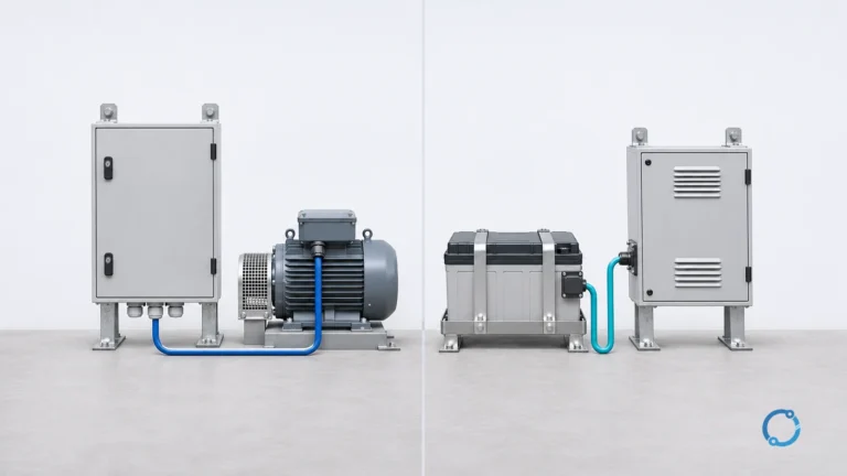

Short answer: A series circuit has one continuous path, so the same current passes through every element, the source voltage divides among the elements and resistance values add. A parallel circuit has multiple voltage-connected paths, so the same voltage appears across every branch, branch currents add and the reciprocal of total resistance equals the sum of the branch reciprocals. For a simple series-parallel network, reduce an inner parallel group to one equivalent resistance, then calculate the remaining series circuit.
Those rules make it possible to answer three common questions without guessing: What current will flow? How does voltage divide? What happens if one path opens or shorts? The following examples use only ideal resistors, fixed voltage sources and stated numerical inputs. Real conductors add resistance, real sources have limits and real components have tolerances, but the connection rules remain the foundation for more detailed analysis.
This page is about circuit relationships. It does not replace overcurrent protection, installation codes or qualified fault diagnosis.
Series versus parallel at a glance
| Relationship | Series connection | Parallel connection |
|---|---|---|
| Number of current paths | One path through all elements | One path through each branch |
| Current | Same through every element | Divides among branches |
| Voltage | Divides among elements and sums to the source voltage | Same across every branch connected to the same nodes |
| Resistance | Adds directly | Reciprocal of total equals sum of reciprocals |
| Open path | Current stops in the entire series path | An open branch stops, while other branches can remain energized |
| Typical structural use | Control device in series with its load; batteries connected to increase voltage | Lighting and receptacle branches sharing a supply; batteries connected to increase capacity |
The table describes ideal connections. A real wiring system can contain a mixture of series and parallel paths, and protective devices may intentionally place a switching element in series with a parallel load group.
Series circuits
Rule 1: current is common
In a series circuit, charge has no alternative route through the connected elements. Whatever current enters one element must leave it and enter the next. Therefore:
I_1 = I_2 = I_3 = I_total
This is a consequence of charge conservation and is a simplified application of Kirchhoff’s current law at a series connection node. If an ideal series circuit has no leakage path, all elements see the same current even when their resistances differ.
Rule 2: voltages add
The source voltage is shared among the series voltage drops. For ideal elements, the signed sum of the drops around the closed path is zero; this is a simplified application of Kirchhoff’s voltage law. When the drops act in the same direction around the source path, their magnitudes add:
V_total = V_1 + V_2 + V_3 + ...
Voltage does not divide equally by default. It divides in proportion to the resistance of each element when the same current flows through every element.
Rule 3: resistance adds
Because the voltage drops add and the current is common:
R_total = R_1 + R_2 + R_3 + ...
Adding more elements in series increases the resistance of the path. The total is always greater than any individual resistance in the series group, assuming every resistance is positive.
Series worked example
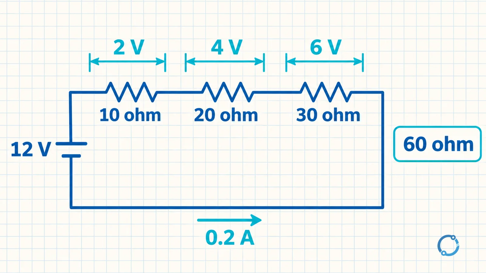
Connect three hypothetical resistors in series:
R_1 = 10 ohmR_2 = 20 ohmR_3 = 30 ohm- Source voltage =
12 V
Find total resistance
R_total = 10 + 20 + 30 = 60 ohm
Find current
Using the Ohm’s law relationship:
I = V / R_total
I = 12 / 60 = 0.2 A
The same 0.2 A passes through each resistor.
Find each voltage drop
V_1 = I x R_1 = 0.2 x 10 = 2 VV_2 = I x R_2 = 0.2 x 20 = 4 VV_3 = I x R_3 = 0.2 x 30 = 6 V
Check the voltage division:
V_total = 2 + 4 + 6 = 12 V
The results are consistent with the source voltage. The largest series resistance produces the largest voltage drop because the current is common.
Parallel circuits
Rule 1: voltage is common
Every branch connected across the same pair of ideal nodes has the same voltage across it:
V_1 = V_2 = V_3 = V_total
This assumes ideal connecting conductors and no significant voltage drop between the common nodes. In real wiring, conductor voltage drop, loose connections and source impedance can create differences, which is one reason a multimeter measurement must be made at the actual points of interest.
Rule 2: branch currents add
The source supplies the sum of the branch currents:
I_total = I_1 + I_2 + I_3 + ...
The current divides according to branch resistance when voltage is common. A lower-resistance branch carries more current, but it does not change the voltage across the other ideal branches in the same parallel group.
Rule 3: reciprocal resistances add
For parallel resistances:
1 / R_total = 1 / R_1 + 1 / R_2 + 1 / R_3 + ...
The equivalent resistance is less than the smallest individual branch resistance, because adding a parallel branch creates another path for current. For two resistors, a convenient shortcut is:
R_total = (R_1 x R_2) / (R_1 + R_2)
That shortcut is only a compact form of the reciprocal relationship. It does not create a new rule.
Parallel worked example
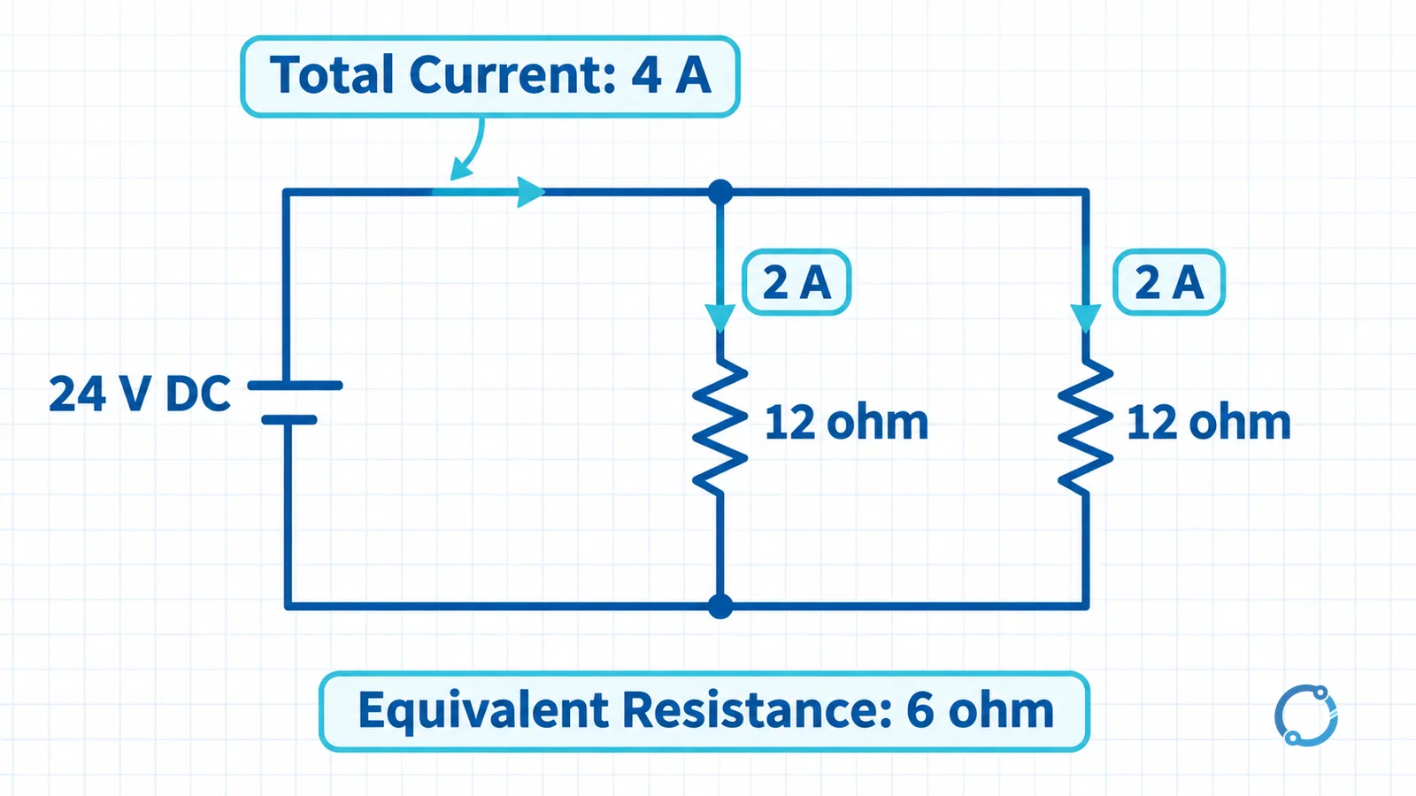
Connect two hypothetical 12 ohm resistors in parallel across 24 V.
Find equivalent resistance
Use the two-resistor form:
R_total = (12 x 12) / (12 + 12)
R_total = 144 / 24 = 6 ohm
The equivalent resistance is 6 ohm, which is less than either 12 ohm branch.
Find each branch current
Each branch receives the full 24 V:
I_branch = 24 / 12 = 2 A
Find total current
I_total = 2 + 2 = 4 A
Check using the equivalent resistance:
I_total = 24 / 6 = 4 A
The two methods agree. The source supplies 4 A, while each branch carries 2 A. The branch currents recombine rather than disappear.
Series-parallel circuits
A series-parallel circuit combines both connection types. Use a two-step reduction:
- Reduce the inner parallel group to one equivalent resistance.
- Redraw the circuit as a series connection and calculate outward from that equivalent value.
Mixed worked example
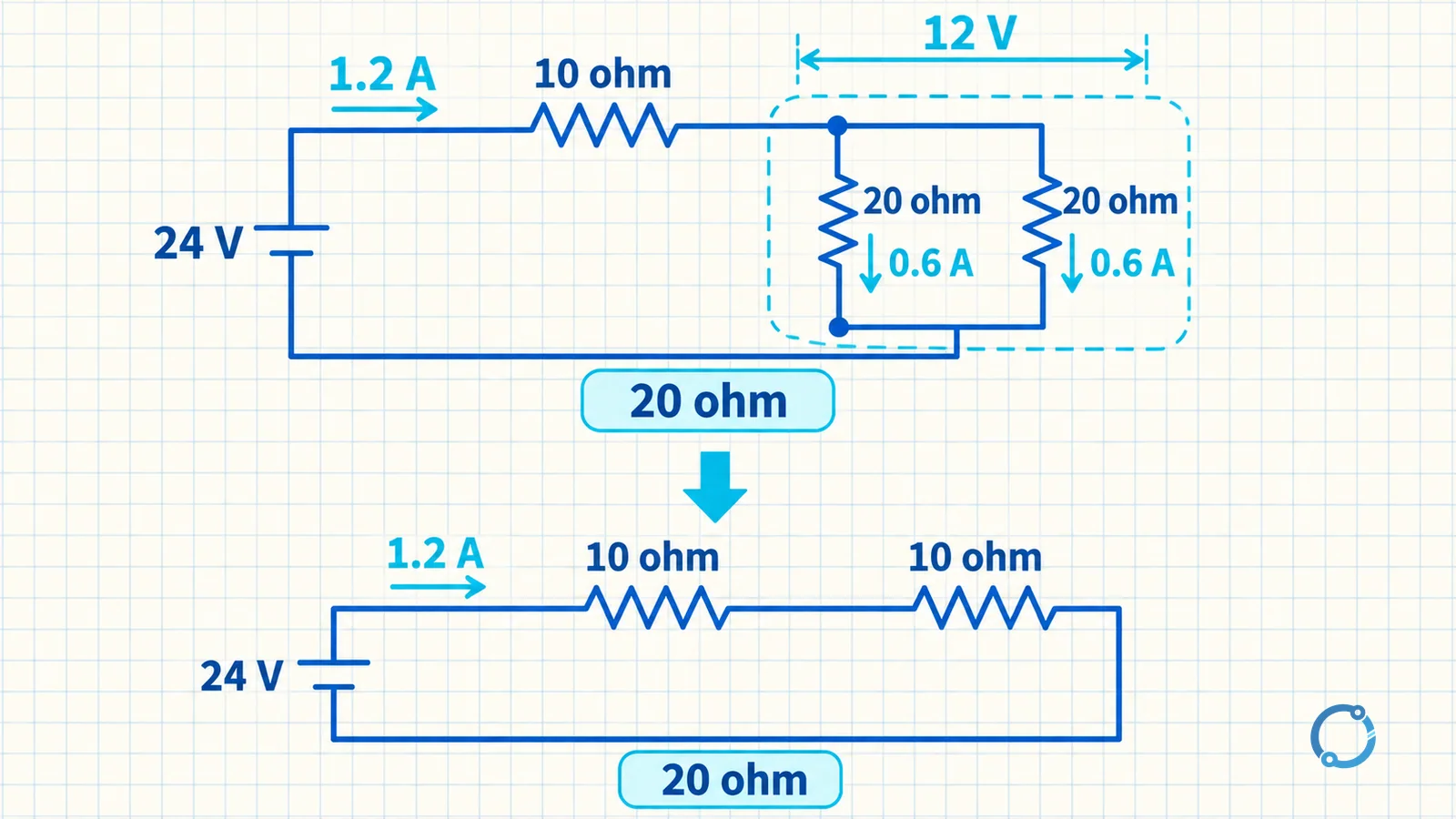
Consider a 10 ohm resistor in series with a parallel group made of two 20 ohm resistors. The complete network is supplied at 24 V.
Start with the parallel pair:
R_parallel = (20 x 20) / (20 + 20) = 400 / 40 = 10 ohm
Now the circuit is equivalent to two 10 ohm resistances in series:
R_total = 10 + 10 = 20 ohm
Find the total current:
I_total = 24 / 20 = 1.2 A
The 1.2 A current passes through the 10 ohm series resistor. Its voltage drop is:
V_series = 1.2 x 10 = 12 V
The remaining voltage across the parallel group is:
V_parallel = 24 - 12 = 12 V
Each 20 ohm branch therefore carries:
I_branch = 12 / 20 = 0.6 A
Check the branch sum:
0.6 + 0.6 = 1.2 A
The order matters. If the parallel group is mistaken for a series pair, the equivalent resistance becomes 40 ohm instead of 10 ohm, and every downstream result is wrong.
What happens when a path opens or shorts
Series open circuit
If one element in a series path opens, the common current falls to zero and every load in that path loses current. A switch, fuse or protective device may intentionally create this condition. A failed open component can create the same effect unintentionally.
Parallel open branch
If one branch of an ideal parallel group opens, the remaining branches can stay energized at the same source voltage. The total current decreases by the current that the open branch had carried, assuming the source voltage remains unchanged. In a real source with significant impedance, voltage and remaining branch currents can change.
Short circuit
A short creates an unintended low-resistance path. In a parallel group it can divert current from other branches and can severely reduce the voltage across the group. In a series path it can remove a voltage drop and increase current elsewhere. Do not calculate a fault result and then work on energized equipment. Isolate the circuit, verify absence of voltage and follow qualified procedures. The role of the difference between an MCB and a fuse is to interrupt overcurrent within the protection design, not to make fault finding safe.
Where series and parallel connections appear
Lighting and receptacle branch circuits are generally arranged in parallel so each load can receive the supply voltage independently and one load can be switched without breaking every other branch. A switch or fuse is placed in series with the load or circuit path whose current must be controlled or interrupted.
Batteries connected in series increase the available terminal voltage in an ideal teaching model. Batteries connected in parallel increase available charge capacity when the cells or packs are designed and rated for parallel operation. Those statements are structural orientation only; battery systems require cell matching, protection, thermal and charging controls that are outside this page.
Series and parallel rules also help explain voltage division, current sharing and the impact of an open or shorted path. They do not cancel voltage drop along real conductors. A conductor can be modeled as a resistance in the circuit, but a complete installation must also consider length, current, material, temperature and connection quality.
Common mistakes
Adding voltages to a parallel group
Parallel branches connected across the same ideal nodes have the same voltage. Do not add their branch voltages as if they were series elements.
Adding resistances directly in parallel
Parallel resistance uses reciprocals. For two 12 ohm branches, the equivalent is 6 ohm, not 24 ohm. The equivalent must be smaller than the smallest branch.
Treating current as common in both connection types
Series current is common; parallel voltage is common. Current divides in parallel and voltage divides in series. Mixing the assumptions produces a circuit that cannot be checked against the source values.
Ignoring the source and conductors
The worked examples use an ideal voltage source and ideal connecting conductors. Real supplies have regulation, conductors have resistance and components have tolerances. Once the ideal connection behavior is understood, the model can be expanded with the fundamental voltage concept and measured values.
A practical checking routine
- Identify the nodes and draw the current paths.
- Mark elements that share the same current as series-connected.
- Mark branches that share the same voltage as a parallel group.
- Reduce the innermost parallel group before calculating the outer series path.
- Calculate total resistance and total current.
- Work back through the network to find branch currents and element voltages.
- Verify that currents recombine and voltage drops sum to the source voltage where applicable.
This routine is intentionally simple, but it scales to more than three examples when the topology stays free of dependent sources and complex magnetic coupling. More advanced networks may require additional circuit laws, measurement or simulation.
FAQ
What stays the same in a series circuit?
The current is the same through every element in a single series path. The voltage drops may differ, and their magnitudes add to the source voltage in the ideal case.
What stays the same in a parallel circuit?
The voltage is the same across each branch connected to the same ideal nodes. The branch currents may differ, and their sum is the total source current.
How do you calculate total resistance in parallel?
Add the reciprocals of the branch resistances and take the reciprocal of the sum. For two resistors, R_total = (R_1 x R_2) / (R_1 + R_2) is the shortcut.
What happens to the other branches when one parallel branch opens?
The other branches can remain energized at the source voltage, while the open branch stops carrying current. The total current falls by the missing branch current if the source voltage does not change.
Why is equivalent parallel resistance smaller than the smallest branch?
Every added parallel branch provides another path for current. The increased total conductance produces a lower equivalent resistance.