
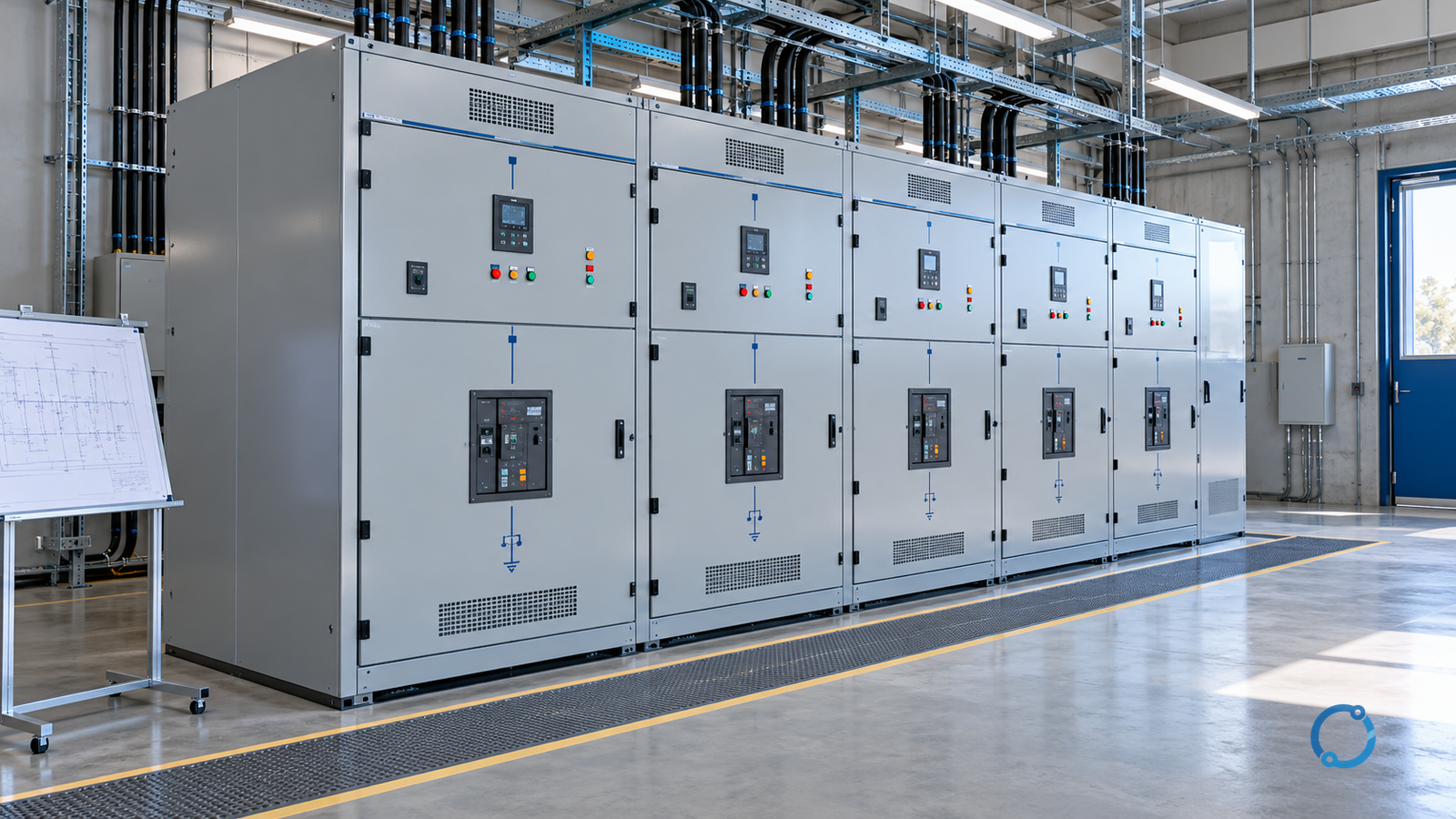
Metal-clad and metal-enclosed medium-voltage switchgear are not two finishes applied to the same assembly. They describe different standards concepts, construction expectations and equipment arrangements. The comparison becomes unreliable when a vendor label, a marketing brochure or a regional habit is treated as proof that an assembly has the required barriers, devices, interlocks or test evidence.
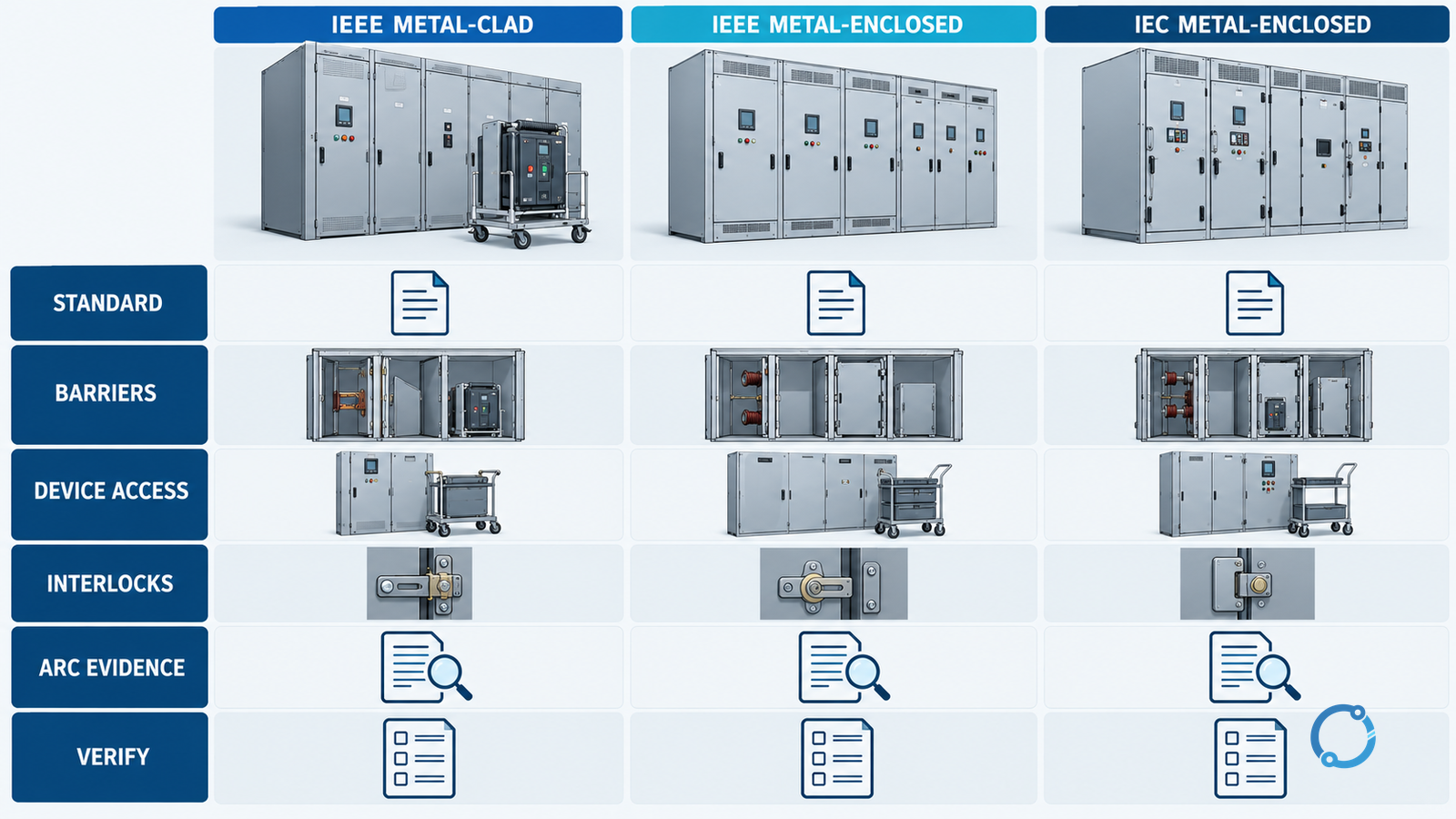
The starting point is the governing project standard. IEEE metal-clad switchgear is a defined IEEE construction category associated with drawout circuit breakers and specific compartment and barrier requirements. IEEE metal-enclosed interrupter switchgear is a broader family that can use different interrupting devices and arrangements. IEC metal-enclosed switchgear is a broad assembly category with its own service-continuity, compartment and internal-arc classification system. These terms do not map one-to-one.
This article compares the engineering questions behind the labels. It does not declare a universal winner, because a well-specified metal-clad assembly can be wrong for one operating philosophy while a metal-enclosed interrupter arrangement can be wrong for another. Safety, maintenance, fault containment and service continuity must be proved for the exact offered product and project.
The short answer: compare duties, not badges
Ask five questions before choosing a category:
- Which standard and edition govern the project?
- Which switching and protection devices are required?
- What must be isolated, viewed, tested or maintained while other sections remain energized?
- What internal-arc, barrier, interlock and service-continuity performance is required?
- What evidence will prove that the offered assembly meets those requirements?
Only after those questions have answers should the team compare enclosures, compartments, breaker withdrawal, cable access, bus arrangements, floor space, ventilation, environmental protection and lifecycle cost.
The switching devices in MV switchgear guide explains why the interrupting device and the assembly are separate decision layers. A high-quality circuit breaker inside an unsuitable assembly is not a complete switchgear solution.
Why the terminology is easy to misapply
“Metal-enclosed” sounds like a general description: metal around energized equipment. In standards, it has a more precise scope. IEC 62271-200 covers AC metal-enclosed switchgear and controlgear above 1 kV and up to and including 52 kV, including its construction, ratings and tests within the edition’s scope. “Metal-clad” in the IEEE C37.20.2 sense is a more specific construction associated with drawout electrically operated circuit breakers and compartmentalized metal barriers.
IEEE C37.20.3 covers metal-enclosed interrupter switchgear above 1 kV AC up to 48.3 kV AC. Its family allows arrangements based on interrupting devices that are not necessarily the same as the metal-clad drawout circuit-breaker concept.
A specification that mixes an IEC assembly requirement with an IEEE metal-clad label can create contradictory expectations. The document may demand a barrier configuration from one standard, a compartment classification from another, and a test result that uses a third basis. Vendors may respond with a compliant product for one interpretation and an unverified assumption for another.
Use the exact standardized definition for the project. Do not translate a category name between systems unless a competent specification engineer has mapped every applicable requirement and the acceptance test evidence.
Comparison dimension 1: assembly and interrupting device
The device arrangement affects operation, protection and spare-parts strategy.
| Decision area | Metal-clad concept in IEEE practice | Metal-enclosed interrupter switchgear concept | IEC metal-enclosed assembly |
|---|---|---|---|
| Governing frame | IEEE C37.20.2, exact edition and project additions | IEEE C37.20.3, exact edition and project additions | IEC 62271-200 with IEC 62271-1 common requirements |
| Primary interrupting duty | Drawout electrically operated circuit breakers within the standard’s scope | One or more interrupter-switch arrangements within the product scope | Depends on the specified switching devices and the complete assembly |
| Protection integration | Relays, CTs, trip circuits and control architecture must be coordinated with the drawout breaker scheme | Protection and switching functions may follow an interrupter-switch arrangement | Can integrate circuit breakers, contactors, switches or combinations within the product design |
| Functional implication | Withdrawal and replacement are central to the operating model | Isolation and switching may follow a different physical workflow | Must be evaluated from the actual single-line and compartment arrangement |
The table is not a cross-standard equivalence. It identifies the features the engineer must verify. A product can contain a withdrawable device without establishing that every IEEE metal-clad construction requirement has been met. A product can be called metal-enclosed without providing the specific functions of IEEE metal-clad switchgear.
For a project with a fixed-device operating strategy, the fixed versus withdrawable MV switchgear comparison is a separate decision. The assembly category should follow the required maintenance and isolation workflow, not precede it.
Comparison dimension 2: barriers and compartments
Barriers are not just sheet-metal panels. They define which energized parts a person can approach during a defined operation, how a fault might propagate, and what can remain accessible when one part of the equipment is isolated.
Record:
- the physical boundary between the main bus and each breaker or switch compartment;
- the barriers around cable and current-transformer compartments;
- the separation between control circuits and high-voltage parts;
- the design of removable covers and inspection windows;
- the path through which pressure, hot gas or arc products would leave an event;
- the materials, bonding and removable-part tolerances;
- the conditions under which a cover can be opened;
- whether barrier performance is part of a declared classification or test result.
An enclosure that looks closed from the front may have a single roof release, a rear cover or a pressure path that changes the maintenance procedure. The site’s operating philosophy must match what can be isolated and accessed safely.
IEEE metal-clad construction includes compartment and barrier expectations tied to its standard. IEC metal-enclosed switchgear uses service-continuity and internal-arc classifications to express particular performance, but the category names alone do not guarantee a desired level. Ask for the exact declaration and the test report, not a generic phrase such as “fully compartmentalized.”
Comparison dimension 3: isolation and drawout operation
A drawout device can move between connected, test and disconnected positions. That can support maintenance and substitution, but it also introduces specific operations:
- racking the device with the correct tool;
- confirming an isolating position and its indicator;
- checking the shutter or barrier that exposes fixed contacts;
- verifying control-circuit disconnection;
- transferring the device safely between the compartment and a service cart;
- confirming the interlock state before operating;
- preventing the device from being inserted into the wrong compartment;
- verifying that no stored spring energy creates an unexpected motion.
Do not assume that “drawout” means “safe to take out.” The isolation, pressure, arc and machine-related hazards must be controlled under the site’s switching and work procedures. The MV breaker operating sequence and MV switchgear commissioning release provide related verification structures.
An interrupter-switch arrangement may use visible isolating gaps, blade-type switches, earthing switches or a different operational sequence. The fact that an isolation means is visible does not remove the need to verify the full circuit and the applicable safety procedure.
Comparison dimension 4: interlocks and operating logic
The question is not whether a vendor advertises interlocks. It is what each interlock physically prevents and how a human or control system could bypass it.
Build an interlock matrix covering:
- opening the device compartment with the device in service;
- moving a drawout device with the breaker closed;
- operating an earthing switch while the isolation point is not confirmed;
- closing a breaker into a closed earthing switch;
- entering a cable compartment while the relevant circuit is live;
- transferring between sources without the required safety and electrical coordination;
- opening a control or power compartment before stored energy is discharged;
- overriding a mechanical interlock for testing, if such a provision exists.
Mechanical interlocks should not be treated as a substitute for administrative control. Likewise, a control-system logic interlock is not necessarily a physical barrier. A good design makes both the intended state and the unintended operation difficult to conceal.
IEC and IEEE standards may require specific interlocks within their scope, but the project’s switching philosophy, network configuration and site procedures determine the complete operating hazard.
Comparison dimension 5: bus, cable and future extension
At the assembly level, examine the route of power from the incoming circuit through the main bus, the branch device and the cable or outgoing cable compartment.
Consider:
- top-entry versus bottom-entry cables;
- front or rear cable access;
- available cable bending radius and termination support;
- phase spacing, barriers and test-point access;
- current-transformer installation and secondary wiring;
- potential transformers and fused or unfused connections;
- busbar joints and their maintenance access;
- future bays, bus ties and extension methods;
- the effect of adding a section on hazard boundaries and access;
- separation of control and power wiring;
- earthing capacity and earthing-switch arrangement.
Two switchgear arrangements with the same front elevation can have very different rear access, cable terminations and bus maintenance. If the site cannot use the cabling arrangement, the category choice may be irrelevant to the real project risk.
The MV cable termination failure guide explains why stress control, creepage and installation geometry must be considered in the space provided by the assembly. A compact enclosure that meets a dimensional rating can still make a reliable termination difficult if the complete installation is not planned.
Comparison dimension 6: maintenance and service continuity
Maintenance is a system activity. Compare how each option supports:
- visual inspection without opening a hazardous compartment;
- breaker testing and replacement;
- cable and CT maintenance;
- busbar inspection and cleaning;
- protective-relay testing;
- secondary circuit work;
- earthing for work;
- isolation of one section while adjacent sections remain energized;
- replacement of a failed electronic trip unit or control module;
- spare-parts availability and lead time;
- condition monitoring and remote diagnostics.
IEEE metal-clad’s drawout and compartment concept may support some maintenance tasks through a defined replacement workflow. That does not make it universally faster to maintain. Floor space, weight, lifting equipment, trolley access, trained staff and spare-device availability can determine the actual downtime.
Metal-enclosed interrupter switchgear can be well matched to simpler switching duties where the operating and maintenance model is more direct. Yet the exact device and assembly still need to be verified. The GIS bay maintenance isolation and restoration guide illustrates how a compact assembly can require a disciplined isolation procedure even when the enclosure appears to simplify access.
Comparison dimension 7: internal arc and environmental protection
Internal-arc performance is not a property that can be inferred from the words “metal-clad” or “metal-enclosed.” It is a declared capability tied to a test arrangement, accessible sides, rating, duration and classification. A product may offer an internal-arc-rated version but not the exact frame, bus or extension being quoted.
Ask:
- which sides of the assembly are tested and accessible;
- what arc current and duration apply;
- what gas path and pressure-relief arrangement are required;
- whether the installation room, duct or exhaust path was designed for the stated release;
- whether low-pressure or pressure-relief devices are correctly installed;
- whether barriers remain effective after cable or bus modifications;
- whether the building’s architectural opening and adjacent equipment are inside the hazard boundary.
Likewise, environmental protection is not reduced to an IP number. Condensation, pollution, altitude, salt, humidity, vermin, dust and solar heating can affect insulation and controls. The complete enclosure, heating, ventilation and cable-entry design must suit the site.
The arc-flash risk reduction guide provides related project checks. Arc rating is only one layer in an electrical safety program.
Comparison dimension 8: operating and fault-current duties
The assembly and the device must be matched to the system:
- nominal and maximum system voltage;
- basic insulation level and lightning impulse withstand;
- continuous bus and branch current;
- short-circuit withstand and peak current;
- interrupting and making capacity of each device;
- fault-clearing time;
- neutral and earthing arrangement;
- capacitive, inductive or generator-source duty;
- switching frequency and duty cycle;
- future load and source growth.
An electrical room can have a fault-current value that is within the breaker’s interrupting rating but outside a bus or cable compartment’s short-time withstand. Conversely, a device with adequate interrupting capacity can be installed in an assembly whose internal barriers or gas path do not meet the required internal-arc classification.
The medium-voltage circuit-breaker ratings crosswalk and ANSI rating comparison explain why ratings from different standards cannot be combined by taking the largest number.
IEC and IEEE terminology: a boundary table
| Question | IEEE metal-clad | IEEE metal-enclosed interrupter switchgear | IEC metal-enclosed switchgear |
|---|---|---|---|
| What is the first evidence? | Exact C37.20.2 edition and complete product construction | Exact C37.20.3 edition and interrupter-switch arrangement | Exact IEC 62271-200 edition and assembly declaration |
| Is compartmentalized construction assumed? | The standard’s defined construction must be met | Verify the exact assembly and barriers | Verify the project’s required partition and service-continuity classification |
| Does the label prove drawout breaker operation? | Do not rely on the label; verify the offered device | Not assumed | Not assumed |
| Does the label prove arc resistance? | No; verify the exact tested classification | No; verify the exact tested classification | No; verify the exact tested classification |
| Can a category name replace a project risk study? | No | No | No |
This table helps prevent the most common error: using a familiar term as a shortcut for a set of unverified requirements.
How to build the selection package
A specification should include:
- Applicable standards, editions and local amendments.
- Single-line diagram and source characteristics.
- Required switching, protection and metering functions.
- Rated voltage, current, short-time and impulse ratings.
- Required device type, operating mechanism and control voltage.
- Compartment, barrier and service-continuity requirements.
- Internal-arc requirement, tested sides and installation assumptions.
- Interlock and operating sequence matrix.
- Cable, bus and future-extension arrangement.
- Environmental and site conditions.
- Required type tests, routine tests, design review and witness tests.
- Spare parts, maintenance access and lifecycle requirements.
Every requirement should identify how the vendor will prove compliance. “Metal-enclosed” or “metal-clad” alone is not a test result.
Factory evidence before shipment
The acceptance plan should verify more than the front nameplate:
- approved drawings and bill of materials;
- device certificates and assembly declarations;
- type-test reports for the exact construction;
- routine-test records;
- protection settings and CT/VT ratios;
- interlock operation through the specified sequence;
- drawout operation and compartment identification;
- internal-arc test evidence and installation assumptions;
- cable and bus termination inspection;
- paint, label, phase identification and earthing;
- handling, lifting and storage instructions;
- shipping splits and site-assembly responsibility.
Witness testing is useful when the project depends on a specific sequence or barrier. It should confirm the actual product, not a representative demonstration disconnected from the ordered assembly. Preserve photographs, test sheets and deviations.
Commissioning is part of the comparison
A construction category can look favorable in a tender and still create problems during commissioning if the site team cannot verify isolation, follow the interlocks, access terminations or test the protection scheme.
Before energization, confirm:
- the installed assembly matches the approved drawings;
- every compartment and barrier is complete;
- the switching and earthing sequence is understood and tested;
- mechanical and electrical interlocks operate as specified;
- protection, CT and trip circuits are proved;
- cable terminations have been inspected and are supported;
- arc-pressure paths and room assumptions are valid;
- labels, phase markings and warning signs are present;
- the site procedures cover normal, abnormal and emergency operation.
Do not energize a switchgear assembly because the factory test certificate exists. The installed system includes the building, cables, earthing, controls, protection, operators and the assumptions made in the design.
The practical conclusion
The difference between metal-clad and metal-enclosed MV switchgear is a difference in standards concepts and verified construction, not a simple quality ranking. A good comparison begins with the governing standard, the required switching and protection devices, the isolation and maintenance workflow, the barrier and internal-arc requirements, and the evidence offered for the exact assembly.
Choose the arrangement that supports the project’s operating philosophy and can prove its electrical, thermal, mechanical and safety performance. Do not accept a category name as a substitute for construction review, test evidence or installation planning. Whether an assembly is metal-clad, metal-enclosed interrupter switchgear or IEC metal-enclosed, the decisive question is the same: does the complete installed system meet the duties and hazards of this site?
Sources
- IEC 62271-200:2021+AMD1:2024 — AC metal-enclosed switchgear and controlgear for rated voltages above 1 kV and up to and including 52 kV
- IEC 62271-1:2017+AMD1:2021 — Common specifications for high-voltage switchgear and controlgear
- IEEE C37.20.2-2025 — Metal-clad switchgear
- IEEE C37.20.3-2023 — Metal-enclosed interrupter switchgear
- OSHA 29 CFR 1910.333 — Electrical safe work practices