Short answer
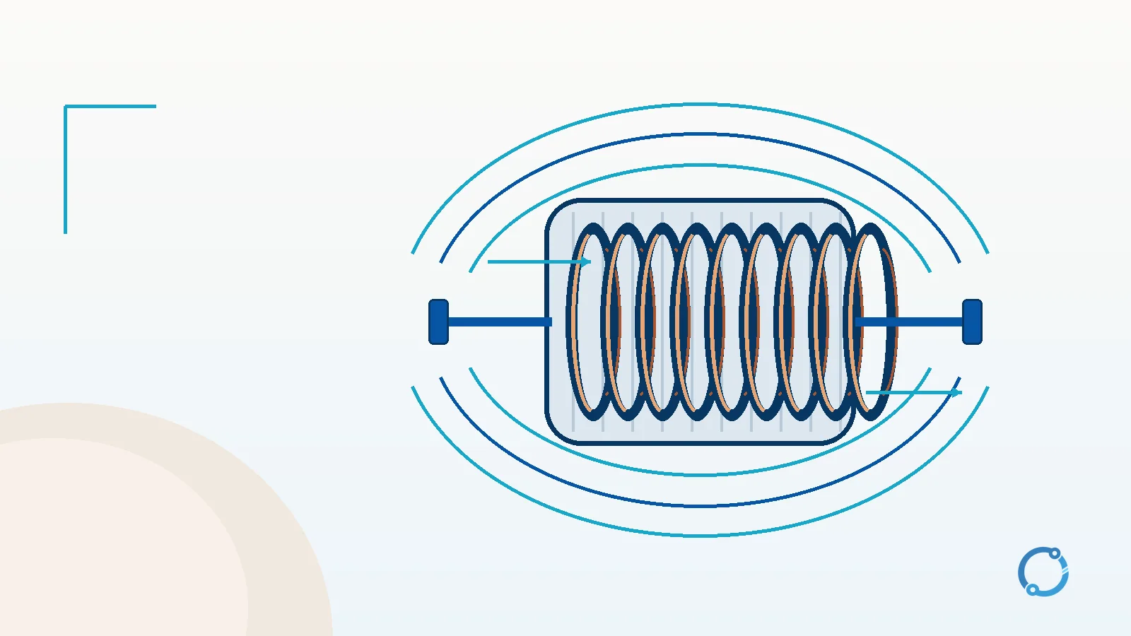
An inductor is a circuit component that stores energy in a magnetic field when current flows through it. Most practical inductors contain a coil of insulated wire, often wound around a magnetic core. The coil concentrates the magnetic field produced by the current.
The defining electrical behavior is not simply that the inductor has a magnetic field. It is that a changing current changes the field, and that changing field induces a voltage which opposes the change in current. In the ideal model, this relationship is written v = L x di/dt. The property L is inductance, measured in henries. This is why an inductor resists a sudden rise in current, releases stored energy when the current falls, and behaves very differently in DC and AC circuits.
What is inside an inductor?
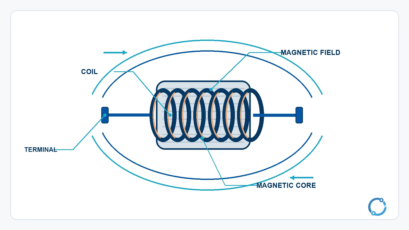
An inductor has three conceptual parts:
- Coil: the winding through which current passes.
- Magnetic core: the material around which the coil is wound, or air in an air-core design.
- Terminals and insulation: the connection points and the insulation that keeps adjacent turns electrically separate.
The coil matters because every current produces a magnetic field. Winding the conductor into many turns places the fields from those turns in a compact region and allows their effects to link the winding. A magnetic core can guide and concentrate the flux, but it also introduces practical limits such as core loss and saturation. An air-core inductor avoids magnetic-core saturation in the ordinary sense, but its field is less concentrated for a given winding.
The simplified relationship for a magnetic-core coil is:
L = mu x N^2 x A / l
Here L is inductance, mu represents the magnetic permeability of the core material, N is the number of turns, A is the effective cross-sectional area of the magnetic path and l is its effective length. The equation is useful as a direction-setting model: more turns, greater effective area or higher permeability tends to increase inductance. It is not a complete design formula for every geometry, and this article does not assign permeability values to particular materials.
Where the magnetic field comes from
When current passes through a conductor, a magnetic field forms around it. In a coil, the field of each turn combines with the fields of the other turns. The resulting magnetic flux passes through the coil and around the complete magnetic path.
The field is not a separate fuel stored in the wire. The energy comes from the source that establishes the current. While current rises, the source does work against the induced voltage. That work becomes energy in the magnetic field. When the current falls, the field collapses and the stored energy can return to the circuit, be transferred to another winding or be dissipated in resistance, depending on the circuit.
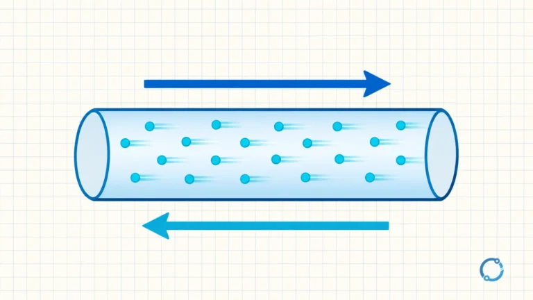
The electric current article explains charge flow and conventional current direction. For an inductor, the important point is that the magnetic field depends on current, and a changing field in turn affects the voltage across the coil.
Inductance and the back-EMF equation
The voltage across an ideal inductor is proportional to inductance and to the rate at which current changes:
v = L x di/dt
In this notation, v is the instantaneous voltage, L is inductance in henries, and di/dt is the rate of change of current in amperes per second. The sign depends on the chosen voltage and current reference directions. Physically, the induced voltage is in a direction that opposes the change in current.
Suppose an ideal 0.5 H inductor carries a current that is rising at 4 A/s. The magnitude of the resulting voltage is:
v = 0.5 H x 4 A/s = 2 V
This does not mean that the inductor always has 2 V across it. It means that, for this assumed constant rate of change, the induced voltage has a magnitude of 2 V. Once the current stops changing, the ideal di/dt term becomes zero and the ideal inductance produces no voltage. A real winding still has resistance and magnetic-core losses, so its measured behavior will differ.
The relationship also explains why an abrupt interruption is significant. If an inductive circuit attempts to change current very quickly, the required voltage can become large. A switch, connector or semiconductor that interrupts the current may therefore be exposed to a voltage rise unless the energy is handled by a designed path. This is a circuit-design and safety boundary, not a suggestion to work on energized equipment.
Energy stored in the magnetic field
For an ideal linear inductor, stored magnetic energy is:
E = 1/2 x L x I^2
Here E is energy in joules, L is inductance in henries and I is current in amperes. Take the same 0.5 H inductor, now carrying a steady 2 A:
E = 0.5 x 0.5 H x (2 A)^2
E = 1 J
The result is one joule. The capacitor article uses a checked example with 7.2 mJ, which is much smaller. Comparing the numbers is a reminder that the henry and the farad are both large units in ordinary electronic work; real components often use millihenries, microhenries or small capacitance values.
Energy rises with the square of current. Doubling the current through the same ideal inductance stores four times as much energy. A real component’s maximum current cannot be increased without limit because the winding, core and thermal design set practical boundaries.
Why current cannot change instantaneously
The phrase “current through an inductor cannot change instantaneously” is an ideal-model statement. In an ideal inductor, a finite voltage produces a finite rate of current change. A discontinuous jump would require an infinite voltage, which no finite source can supply.
Real circuits are not discontinuous ideal systems. Parasitic capacitance, switch breakdown, arc behavior and component limits all matter. The ideal rule is still valuable because it predicts why an inductor opposes a sudden change, why it can produce a large transient voltage when the current path is interrupted, and why current often continues through a freewheeling path immediately after a switch turns off.
The practical consequence is to plan the current path for both the on-state and the interruption state. A conductor, diode, switch or contact must not be asked to absorb the field energy accidentally. The exact protective arrangement depends on the circuit and should be verified by a qualified designer.
This distinction is also why a coil can appear harmless in a low-voltage control circuit yet produce an unexpected transient when its current path opens. The energy is small in many electronic circuits, but the resulting voltage depends on the circuit and the speed of the interruption. Use the actual winding, switching device and suppression network when assessing the duty.
What happens on DC
After a DC source has been connected long enough, the current approaches a steady value. In the ideal inductor, di/dt becomes essentially zero, so the induced voltage becomes zero and the component behaves like a short circuit. Real copper winding has resistance, so a practical inductor behaves like the winding resistance plus any remaining inductive effect.
The approach to steady state is not instantaneous. The ratio of inductance to circuit resistance gives the RL time constant:
tau = L / R
The time constant describes the characteristic rate of the exponential current rise or decay. This article does not need a second numerical example: the important mechanism is that a larger inductance or smaller resistance gives a slower current change. The field builds, the rate of change falls and the current approaches its final value.
This behavior is why an inductor can act as a short-term current smoother. It does not create energy or guarantee a constant current. It stores energy while current rises and returns energy while the current tries to fall. The series and parallel circuits article covers the circuit-analysis rules that sit underneath these observations.
Inductors in series and parallel
When inductors are sufficiently separated that their magnetic fields do not couple significantly, ideal inductors combine like resistors:
L_series = L1 + L2 + L3 + ...
Two 10 mH inductors in series therefore give:
10 mH + 10 mH = 20 mH
For parallel inductors:
1 / L_parallel = 1 / L1 + 1 / L2 + ...
Two 10 mH inductors in parallel give:
1 / L_total = 1 / 10 + 1 / 10 = 2 / 10
L_total = 5 mH
The no-coupling condition is important. Coils mounted close together can share magnetic flux, and mutual inductance may make the simple formulas wrong. A transformer is deliberately built around strong magnetic coupling between windings. The transformer explainer shows how shared magnetic flux links two coils; for standalone inductors, layout and orientation therefore matter.
Inductors in AC circuits
In an AC circuit, current changes continuously, so the induced voltage is continuously present. For an ideal sinusoidal inductor, the opposition to current is called inductive reactance:
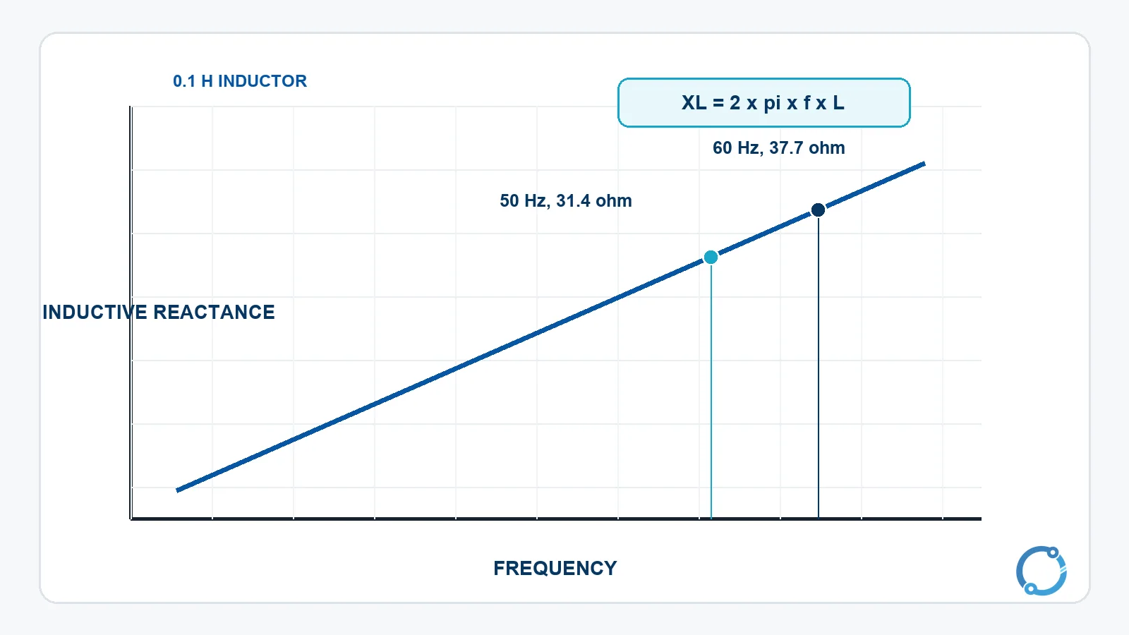
XL = 2 x pi x f x L
Here XL is reactance in ohms, f is frequency in hertz and L is inductance in henries. For L = 0.1 H at 50 Hz:
XL = 2 x pi x 50 x 0.1
XL = 31.4 ohm, approximately.
At 60 Hz:
XL = 2 x pi x 60 x 0.1
XL = 37.7 ohm, approximately.
The same inductance therefore presents more opposition at the higher frequency. This is the opposite trend to a capacitor, whose reactance falls as frequency rises. The difference comes from the underlying storage mechanism: an inductor stores magnetic-field energy and responds to the rate of current change, while a capacitor stores electric-field energy and responds to the rate of voltage change.
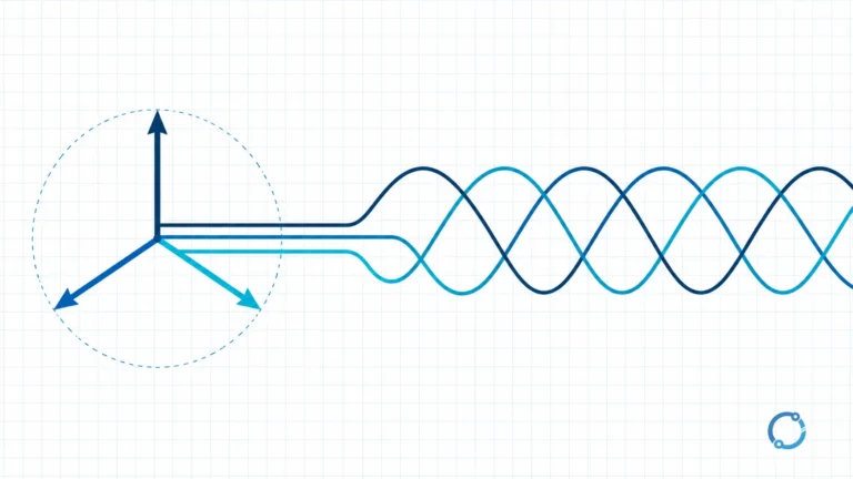
In the ideal pure inductor, current lags the applied voltage by 90 electrical degrees. The power factor article explains why that phase difference produces reactive power and why a lagging current is associated with inductive loads. Real coils have resistance, core loss and interwinding capacitance, so their measured phase angle is not exactly 90 degrees.
Core types and practical limits
An air-core inductor uses a non-magnetic path, while a magnetic-core inductor uses a material that concentrates flux. A ferrite core is common in higher-frequency electronics; laminated iron cores are used in some lower-frequency applications. These are broad construction families, not interchangeable parts. Core material, winding geometry and operating frequency determine the useful behavior.
Saturation is a key limitation. As the magnetic flux in a core increases, the material can reach a region where a further increase in current produces much less increase in flux. The effective inductance can fall, so the current may rise faster than a simple linear model predicts. The article does not publish a saturation current because it is a property of a specific core, winding and temperature.
Real inductors also have winding resistance, core loss, stray capacitance and thermal limits. At high frequency, the winding may not behave like a simple conductor, and the electric field between turns can create unwanted coupling. A part that works at one frequency can be unsuitable at another even if its nominal inductance is unchanged.
Inductors, motors, generators and transformers
An inductor is a component, but the same magnetic principle appears inside larger machines. The electric motor explainer shows how magnetic fields produce torque, while the generator explainer shows how rotating magnetic fields produce voltages. A transformer uses two coupled windings and is built deliberately to transfer energy through a shared magnetic flux.
The comparison helps prevent a common misunderstanding: not every coil is used as a simple standalone inductor, and not every magnetic device is called an inductor in a schematic. The function depends on construction, application and how the magnetic field is linked. A motor winding may have inductance, but its main job is electromechanical energy conversion, not filtering a small signal.
Common misconceptions
First, an inductor is not a “magnetic battery” that holds a fixed amount of energy regardless of current. Its stored energy depends on the current and its inductance, and a practical component has losses and limits.
Second, an inductor does not block AC and pass DC in the way a switch does. Its reactance increases with frequency, so its opposition becomes greater as the current changes faster. At DC steady state, the ideal current is limited by the rest of the circuit and the winding resistance, not by an open circuit.
Third, the formula v = L x di/dt does not mean that a larger voltage always produces a larger steady current. It describes the voltage needed to change current at a particular rate. Steady-state current is determined by the full circuit, including resistance and the source.
Frequently asked questions
What is an inductor in simple terms?
An inductor is a coil-like component that stores energy in a magnetic field when current flows. It opposes changes in current because a changing current induces a voltage in the coil.
Why does an inductor oppose current changes?
The changing current changes the magnetic flux. Under Faraday’s law and Lenz’s law, the changing flux induces an electromotive force whose polarity opposes the change that produced it.
Does an inductor block DC?
An ideal inductor does not block steady-state DC. Its induced voltage becomes zero after the current stops changing, so its opposition is ideally zero. A real winding has resistance, and the rest of the circuit determines the final current.
What is the difference between inductance and inductive reactance?
Inductance L is a property of the component and is measured in henries. Inductive reactance XL is the frequency-dependent opposition to alternating current and is measured in ohms. The two are related by XL = 2 x pi x f x L.
What happens when an inductor is disconnected?
The current change can produce a large induced voltage. The stored magnetic energy needs a controlled path, or it may stress switch contacts, insulation or another component. The exact protection depends on the circuit and must be designed and verified by a qualified person.