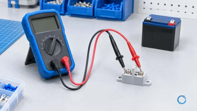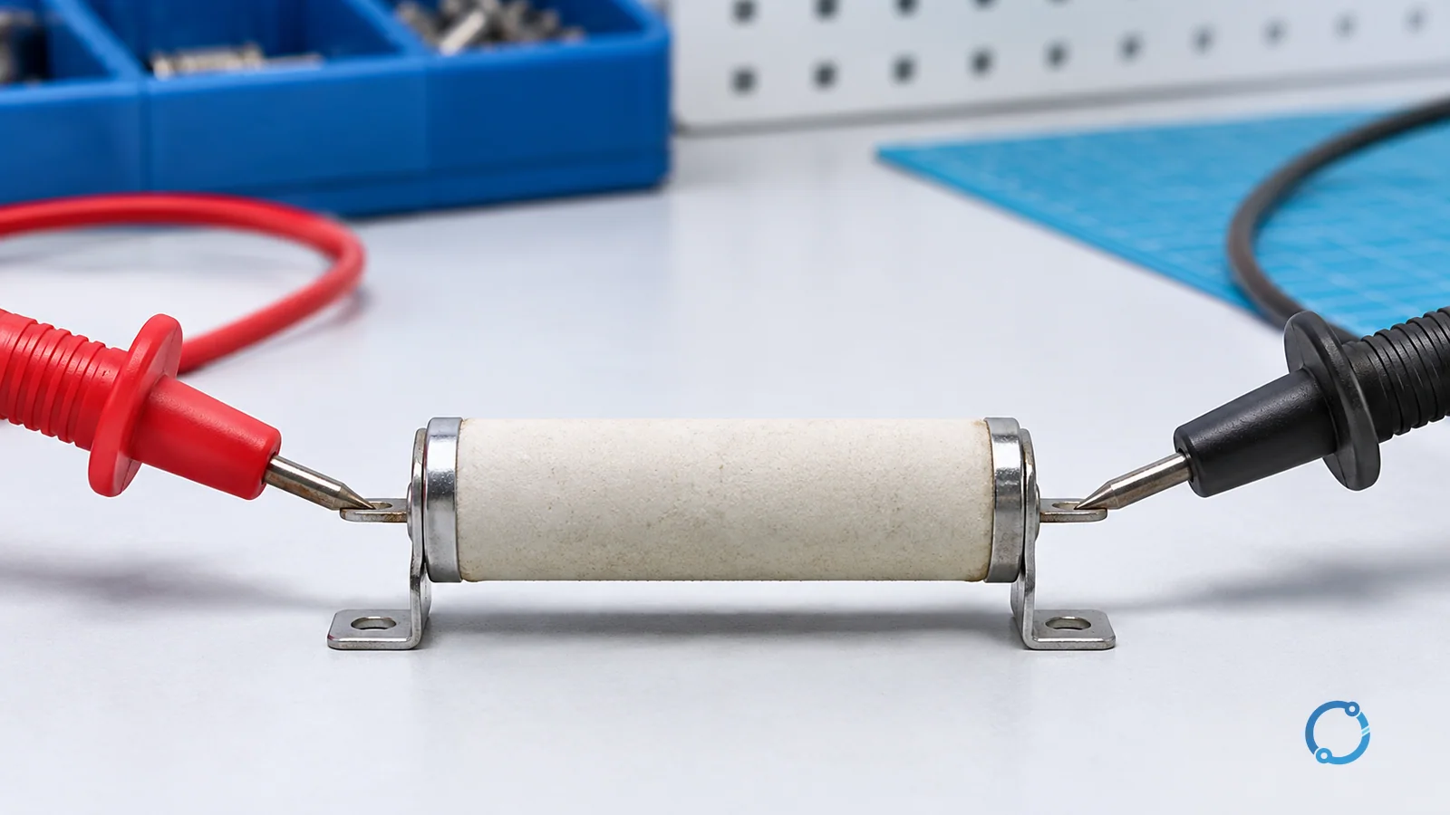
Ohm’s law relates voltage, current, and resistance in a circuit element:
V = I R
In this form, V is the voltage across the element in volts, I is the current through it in amperes, and R is the resistance in ohms. The relationship is a starting point for many DC and resistive-circuit calculations, but it is not a universal description of every electrical device.
The U.S. Department of Energy electrical-science handbook gives three equivalent forms of Ohm’s law and defines the units. It also uses simple worked examples to show that any one quantity can be found when the other two are known.
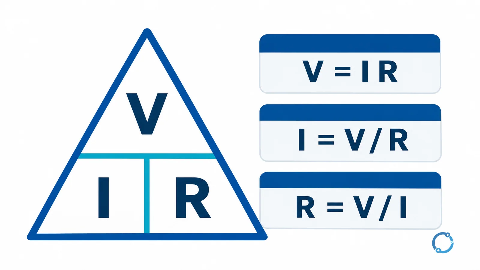
The Ohm’s law triangle
The formula triangle is a memory aid:
      V
    -----
    I   R
Place V at the top. Place I and R side by side below it. To solve for a quantity, cover that quantity with your finger:
- Cover
Vand the remaining symbols sit side by side, givingV = I R. - Cover
Iand the remaining pair isVoverR, givingI = V / R. - Cover
Rand the remaining pair isVoverI, givingR = V / I.
The triangle is only a memory device. The real conditions are the circuit being modeled, the measurement reference, and whether the element behaves approximately as a linear resistance over the relevant operating range.
Units and symbols
| Quantity | Symbol | Unit | Unit abbreviation | What to check before calculating |
|---|---|---|---|---|
| Voltage | V |
volt | V | Is the value AC or DC, RMS or peak, and measured across which two points? |
| Current | I |
ampere | A | Is the current in the same element and operating condition as the voltage? |
| Resistance | R |
ohm | ohm | Is the element linear, and is the resistance appropriate for the operating temperature? |
| Power | P |
watt | W | Power is a separate quantity and should not be confused with resistance |
Use one unit system throughout. Convert milliamperes to amperes and kilohms to ohms before substituting. A result with the wrong power of ten usually comes from a unit conversion, not from the formula itself.
Worked example 1: current from voltage and resistance
Assume a 6 ohm resistive element has 12 V across it. These are teaching values, not a measured product result.
I = V / R
I = 12 V / 6 ohm = 2 A
The current through the element is 2 A under the stated assumption. The result does not tell you the source’s total current if the element is part of a larger parallel or series circuit.
Worked example 2: voltage from current and resistance
Assume a 24 ohm resistor carries 0.5 A.
V = I R
V = 0.5 A x 24 ohm = 12 V
The voltage across the resistor is 12 V. The same current could exist in another part of a series circuit while a different voltage appears across a different element.
Worked example 3: resistance from voltage and current
Assume a component has 24 V across it while 3 A flows through it.
R = V / I
R = 24 V / 3 A = 8 ohm
The calculation gives an equivalent resistance of 8 ohm at that operating point. It does not prove that the component is a fixed 8 ohm resistor at every voltage, temperature, or frequency.
What the result means in a circuit
Ohm’s law is local to the element being described. A series circuit has the same current through its elements, but the voltage divides according to their resistances. A parallel circuit has the same voltage across its branches, but the current divides according to the branch paths. Before substituting values, identify the element and mark the voltage polarity and current direction consistently.
The introduction to voltage explains the measurement reference and the difference between voltage and current. Those definitions matter because a formula cannot correct a probe placed across the wrong points or a current measured in the wrong branch.
Where Ohm’s law stops being enough
Nonlinear devices
A diode, varistor, filament lamp, and many electronic components do not have one constant resistance across their full operating range. Their current-voltage relationship may be curved, polarity-dependent, or temperature-dependent. A single ohmmeter reading taken at low test energy may not predict the energized operating point.
For these devices, use the manufacturer’s characteristic data or the appropriate device model. Do not force a linear resistance onto a curve merely because the arithmetic produces a number.
Changing resistance
Conductor and component resistance can change with temperature. A cold filament can have a very different resistance from a hot filament. A motor winding changes with temperature and operating state. The resistance marked on a component or measured with a small test current is a reference point, not a universal constant.
AC circuits and impedance
An AC circuit can contain inductance and capacitance as well as resistance. The opposition to current may then be described by impedance, and the voltage and current may not peak at the same time. Ohm’s law in the simple V = I R form is not a complete AC network model. Use the applicable impedance method and waveform definitions.
Unit mixing
The common errors are straightforward:
- using 20 mA as
20instead of0.020 A; - using 4.7 kilohm as
4.7instead of4700 ohm; - mixing an RMS voltage with a peak current;
- treating a line-to-line voltage as if it were the voltage across a single component;
- using a nameplate voltage as the actual voltage at the terminals under load.
Write the unit beside every input and cancel it explicitly. This catches many mistakes before a calculator is used.
Measuring resistance while energized
Never use a resistance or continuity mode on a circuit that may be energized. The meter applies its own test signal and expects a de-energized, isolated path. A live circuit can damage the meter, produce a misleading reading, or create a hazard. Isolate, verify dead, discharge stored energy, and remove parallel paths before testing. The circuit-breaker sizing guide shows why a load calculation also needs protection and installation checks.
A quick calculation checklist
- Draw the element and mark the two voltage points.
- Identify the current path and its direction.
- Convert all values to volts, amperes, and ohms.
- Choose the form of the equation that isolates the unknown.
- Substitute and carry units through the arithmetic.
- Ask whether the device is linear at that operating point.
- Check the result against the circuit’s source and other elements.
This checklist is also useful when Ohm’s law is used inside a larger calculation. For example, the induction motor calculations for VFD users involve frequency, speed, torque, and power relationships that a simple resistive formula cannot replace. The distance-protection impedance guide is another boundary: protection engineers work with complex impedance and system quantities, not only a DC resistor.
FAQ
What is the Ohm’s law triangle?
The triangle places V above I and R. Cover the unknown: V = I R, I = V / R, or R = V / I. It is a memory aid, not a replacement for checking units and device behavior.
What are the units in Ohm’s law?
Voltage is in volts, current is in amperes, and resistance is in ohms. Convert prefixes such as milli and kilo before calculating.
Does Ohm’s law work for AC circuits?
The simple resistive form works only when resistance is an adequate model. AC circuits with inductance or capacitance generally require impedance and phase-aware analysis.
Why does my calculated resistance differ from the meter reading?
The meter may test at a different current, temperature, or signal than the operating circuit. The component may also be nonlinear, have parallel paths, or change with temperature.
Can I measure resistance on a live circuit?
No. Resistance and continuity measurements require an isolated, de-energized circuit. Verify the circuit is dead and discharge stored energy before testing.