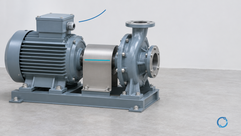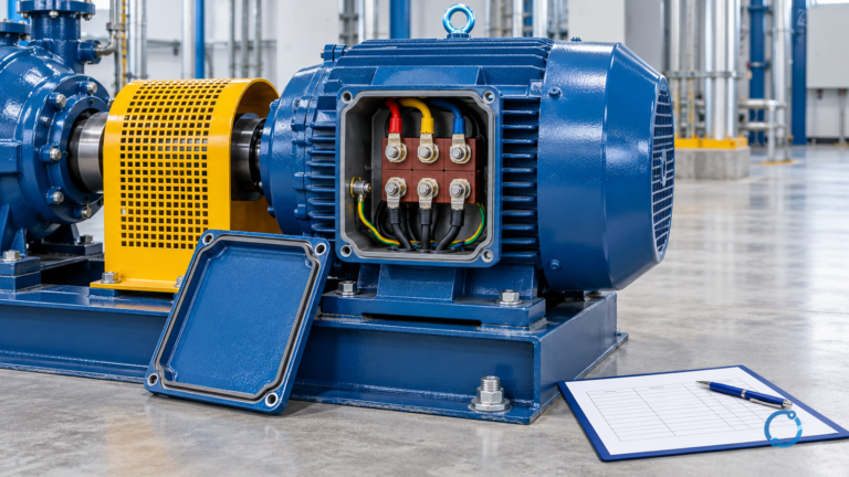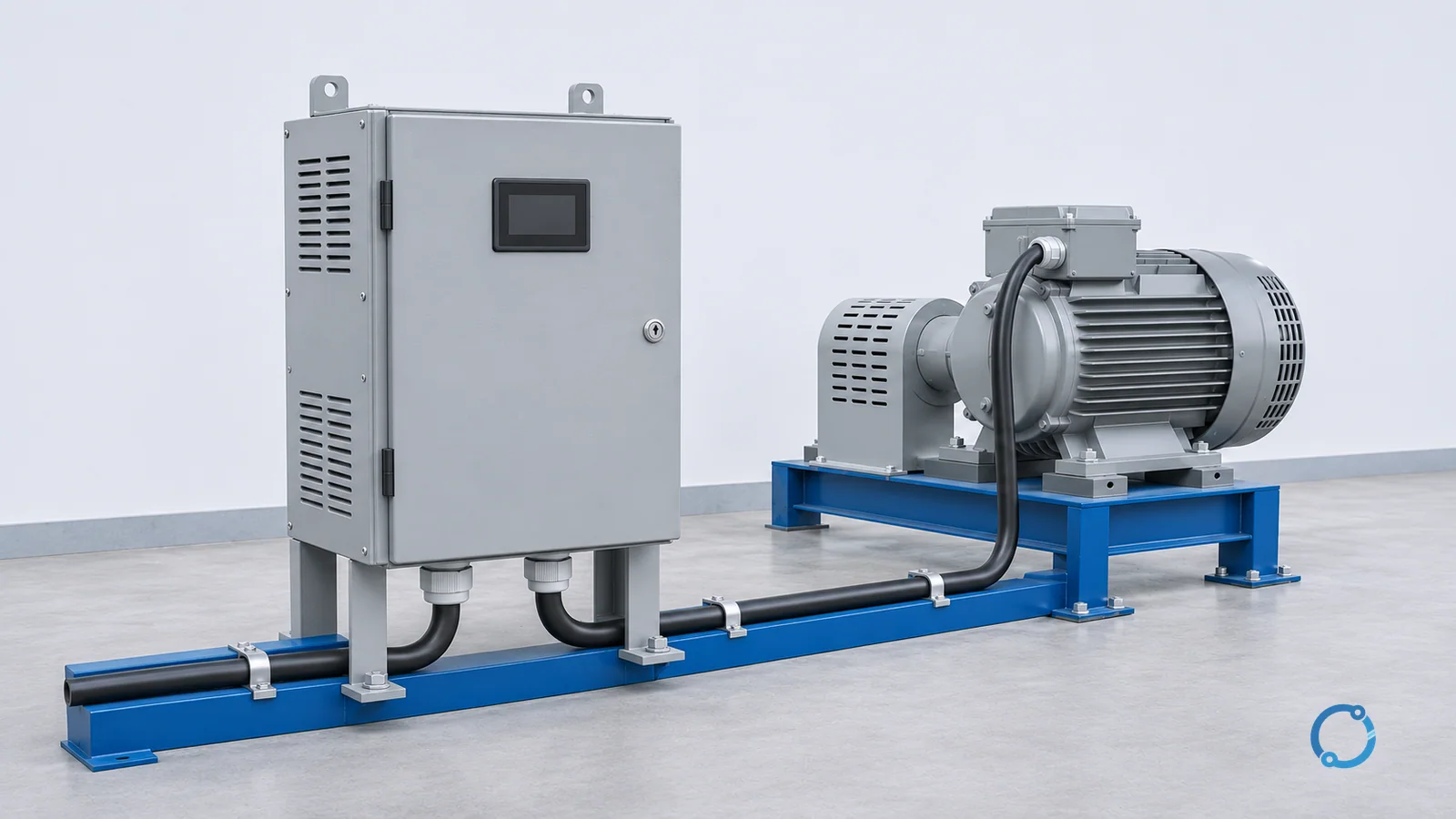
Short answer: A variable frequency drive (VFD) is a power-electronic device that changes the frequency and voltage supplied to an AC motor so the motor can operate at different speeds. It is not simply a soft starter. A soft starter primarily manages starting and stopping, while a VFD can continuously adjust the motor’s operating point during normal running.
That definition sounds simple, but the useful engineering question is more specific: what happens inside the drive, why do frequency and voltage need to move together, and which loads actually benefit from that capability? A VFD is one part of a motor system, not a universal efficiency accessory.
The three power stages
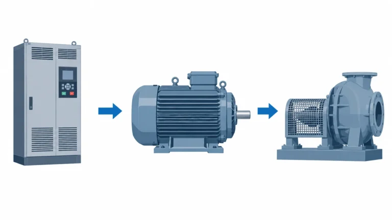
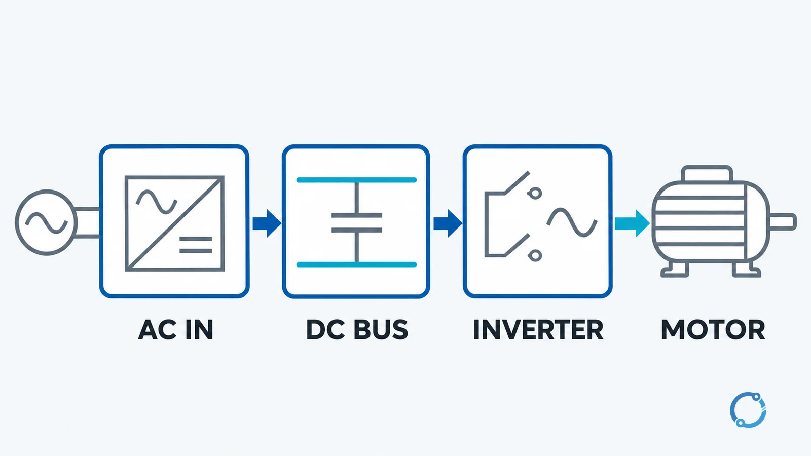
A useful teaching model divides a basic VFD into three stages:
- Rectifier stage: incoming AC is converted into DC.
- DC bus: capacitors and other bus components smooth the rectified voltage and provide an intermediate energy buffer.
- Inverter stage: switching devices reconstruct an AC output whose frequency and voltage can be controlled.
The rectifier may be a diode bridge or an active converter, depending on the drive design. The inverter commonly uses insulated-gate bipolar transistors (IGBTs) or other power switches and pulse-width modulation (PWM) to create a waveform that approximates the desired motor supply. These are common conceptual examples, not a requirement that every drive use the same topology.
The intermediate DC link is important because it separates the incoming supply frequency from the output frequency. Without that intermediate stage, a direct connection to the grid would have a fixed frequency. The drive creates a controlled output, but it also introduces conversion losses, switching behavior and application questions that do not exist with a direct-on-line motor.
The sizing and application guide covers the selection inputs that turn this architecture into a specification. For this article, the important point is the role of each stage: AC enters, is converted to DC, and is then rebuilt as a controlled AC output.
Why the voltage and frequency change together
An AC induction motor develops a rotating magnetic field from the stator supply. The field speed, called synchronous speed, depends on the supply frequency and the number of motor poles:
Ns = 120f / P
Here, Ns is synchronous speed in revolutions per minute, f is frequency in hertz, and P is the number of poles. The rotor normally runs slightly slower than the rotating field; that difference is called slip. Slip is part of induction-motor operation, but it is not the same as the commanded speed of the drive.
If the frequency alone were reduced while the voltage stayed at its original value, the motor’s magnetic operating point would shift. In a basic volts-per-hertz control scheme, the drive reduces voltage approximately in proportion to frequency so that the magnetic flux stays within the intended region. The phrase “V/f control” refers to that relationship.
Worked example: four-pole synchronous speed
Take a four-pole motor supplied at 60 Hz:
Ns = 120 x 60 / 4
Ns = 1800 rpm
At 30 Hz:
Ns = 120 x 30 / 4
Ns = 900 rpm
The synchronous-speed value is not necessarily the measured shaft speed. The rotor will generally run below it by an amount related to load and motor design. The calculation shows the direction and ratio of the speed change, not a guarantee of exact speed under every load.
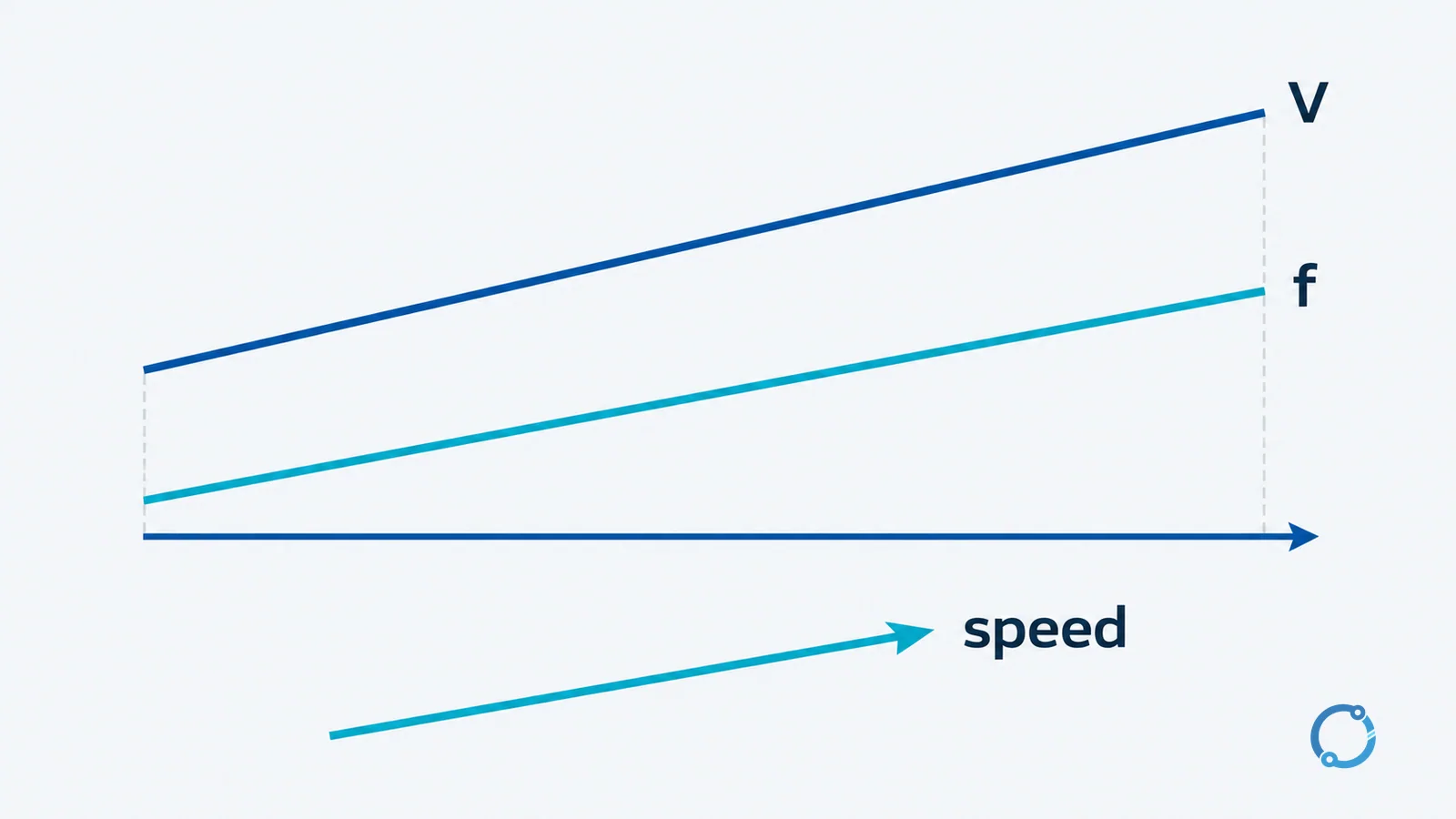
The induction-motor calculation guide explores related relationships such as torque, power and operating points. A VFD changes the supply conditions, but the motor and load still determine whether the resulting operating point is useful.
What a VFD is not
A VFD is not the same as a soft starter. A soft starter limits the voltage during starting and then, in a typical application, leaves the motor connected to the supply for normal running. Its main job is to reduce starting current or control the starting torque profile. A VFD remains in the power path during running and can vary the output frequency.
That distinction matters when someone says “the motor only needs a smoother start.” If the process only needs a controlled start and then runs at a fixed speed, a soft starter may be a better fit. If the process needs to run at different speeds or follow a changing demand signal, a VFD provides a capability that a conventional soft starter does not provide by itself.
Equipment categories can overlap, and electronic motor controllers have many functions. Use the manufacturer’s actual product documentation for a specific unit rather than assuming that a device has a function because it is called a drive or a starter.
Where a VFD fits in the system
A drive sits between the available supply and the motor. It receives a speed or torque reference from a control system, a local keypad, a process controller or another source. The drive measures motor current and other internal quantities, compares the result with its control objective, and adjusts its output switches. The exact control method may be volts-per-hertz, sensorless vector control, closed-loop vector control or another scheme.
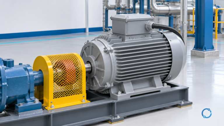
The motor is not the only load on the drive. The driven machine may be a fan, pump, compressor, conveyor, mixer or another mechanical load. The load’s torque-speed curve determines how much torque is needed at each speed, and the motor’s thermal capability determines how long it can supply that torque. A VFD cannot make an undersized motor suitable for a demanding load merely by displaying a different speed.
The electrical environment also matters. A drive is a nonlinear load and can produce harmonic currents and high-frequency switching effects. The harmonic mitigation guide addresses that system-level issue. Cable length, motor insulation, grounding, filtering and drive configuration may need review, especially in a retrofit.
Load torque: the first selection question
A useful first pass classifies the load by how torque changes with speed:
| Load category | Typical behavior | Common examples | What to check |
|---|---|---|---|
| Variable torque | Torque tends to rise with speed, often in a nonlinear relationship | Fans and centrifugal pumps | The operating range, static head and actual system curve |
| Constant torque | Torque is required over the running speed range | Conveyors, positive-displacement pumps, some mixers | Breakaway torque, overload duration and motor thermal margin |
| Constant power | Power demand stays broadly constant while torque falls as speed rises | Some machine-tool and winding applications | The motor’s field-weakening capability and the load’s speed range |
These categories are starting points, not a substitute for the machine’s torque-speed curve. A fan or pump is often described as variable torque, but a system with a high static head or a different control objective may not follow a simple theoretical curve. The motor and machine-load sizing guide develops those inputs.
For a fan or centrifugal pump, reducing speed generally reduces flow and pressure, and the required power tends to fall substantially as speed decreases. The exact relationship depends on the system and the operating point; this article intentionally does not assign a savings percentage. The engineering case for a VFD is strongest when the process genuinely needs variable flow or pressure and the system curve supports efficient operation.
When a motor may need a VFD
A VFD is worth evaluating when one or more of these conditions apply:
- The process needs a controllable operating speed rather than a fixed speed.
- Starting at full line voltage would create an unacceptable current or mechanical transient for the motor, coupling or driven machine.
- A fan, pump or compressor must follow a variable demand instead of running at a fixed output.
- The controller needs to integrate speed, torque or process feedback with a larger automation system.
- The application needs controlled acceleration, deceleration or stopping behavior beyond a simple start/stop command.
- The mechanical system can operate efficiently over a useful speed range, and the motor can tolerate the resulting electrical and thermal conditions.
The word “need” should still be tested. A VFD adds power conversion, controls, parameters, cooling requirements and potential failure points. If the motor runs at a constant speed at its efficient operating point, the drive may provide little process benefit while adding losses and maintenance scope.
When a VFD may not be justified
A fixed-speed load that already starts acceptably may not need a VFD. A simple fan that always runs at full output, a conveyor that only needs a guarded start and stop, or a motor that is already well matched to a constant process may be better served by a direct-on-line starter or a soft starter, depending on the system requirements.
The decision is not just “does the motor move slower?” It is “does the process gain something from controlling the speed, and can the complete motor-drive-load system deliver that benefit over its expected operating range?” A drive can reduce energy use in a suitable variable-flow application, but it can also consume energy and create harmonic or thermal issues when applied without a clear operating case.
Before choosing a drive, verify the motor’s insulation system, winding configuration, cooling at low speed, bearing currents where relevant, cable arrangement, grounding and the drive’s harmonic compatibility. Those checks belong to the detailed application review and are not settled by a generic product category.
Common misconceptions
“A VFD always saves energy”
No. A VFD changes the way the motor is supplied and can improve part-load operation for some loads, especially fans and pumps that genuinely follow a variable demand. If the load runs at a constant speed, the added conversion stage can increase losses and complexity. Measure or model the actual load profile rather than applying a blanket savings claim.
“A VFD is just a soft starter with a speed knob”
They are different functions. A soft starter primarily controls starting; a VFD remains active during running and can vary frequency and voltage. Some products may combine features, so verify the actual equipment’s capabilities and your control objective.
“Adding a VFD requires no review of the motor or cable system”
A drive changes the voltage waveform and introduces high-frequency switching. Motor insulation, cable length, grounding, bearing current and harmonic behavior can matter. The exact requirements depend on the drive, motor, cable and installation, so a retrofit should be reviewed as a system rather than treated as a plug-in accessory.
A practical decision sequence
Start with the process and work back to the equipment:
- Define the required speed, torque and operating time at each condition.
- Plot or obtain the driven machine’s torque-speed and power-speed requirements.
- Check whether the motor can produce the required torque without exceeding its thermal or electrical limits.
- Decide whether speed control is genuinely required or whether starting control is the actual need.
- Review the drive’s supply, harmonic, grounding, cable and environmental requirements.
- Verify the selected drive can coordinate with the motor, protection and control system.
- Commission the operating points and record the verified settings outside this article’s generic scope.
The sequence avoids a common error: selecting a drive first and then searching for a reason to use it. The process need should create the drive requirement, not the other way around.
FAQ
What does a VFD do to an AC motor?
It changes the frequency and voltage supplied to the motor so the motor can operate at a controlled speed. The exact control mode depends on the drive and application. A VFD does not alter the fundamental design of the motor or remove the need to check motor and load compatibility.
How does a VFD change AC into a different frequency?
A basic drive rectifies incoming AC to a DC bus and then uses an inverter to reconstruct an AC output. The inverter switches to create a waveform whose effective frequency and voltage are controlled by the drive. The intermediate DC stage separates the input frequency from the output frequency.
What is the synchronous speed of a four-pole motor at 60 Hz and 30 Hz?
Using Ns = 120f / P, a four-pole motor has a synchronous speed of 120 x 60 / 4 = 1800 rpm at 60 Hz and 120 x 30 / 4 = 900 rpm at 30 Hz. The actual shaft speed is normally a little lower because of slip.
Why does a VFD reduce voltage when it reduces frequency?
In a basic V/f control scheme, the drive reduces voltage approximately in proportion to frequency to keep the motor’s magnetic operating region within its intended range. The exact relationship and available control modes depend on the drive and motor. A generic V/f statement is not a substitute for the manufacturer’s setup requirements.
Is a VFD the same as a soft starter?
No. A soft starter primarily controls the motor during starting, while a VFD remains in the power path and can vary the motor’s running speed. The correct choice depends on whether the process needs speed control, starting control or both.