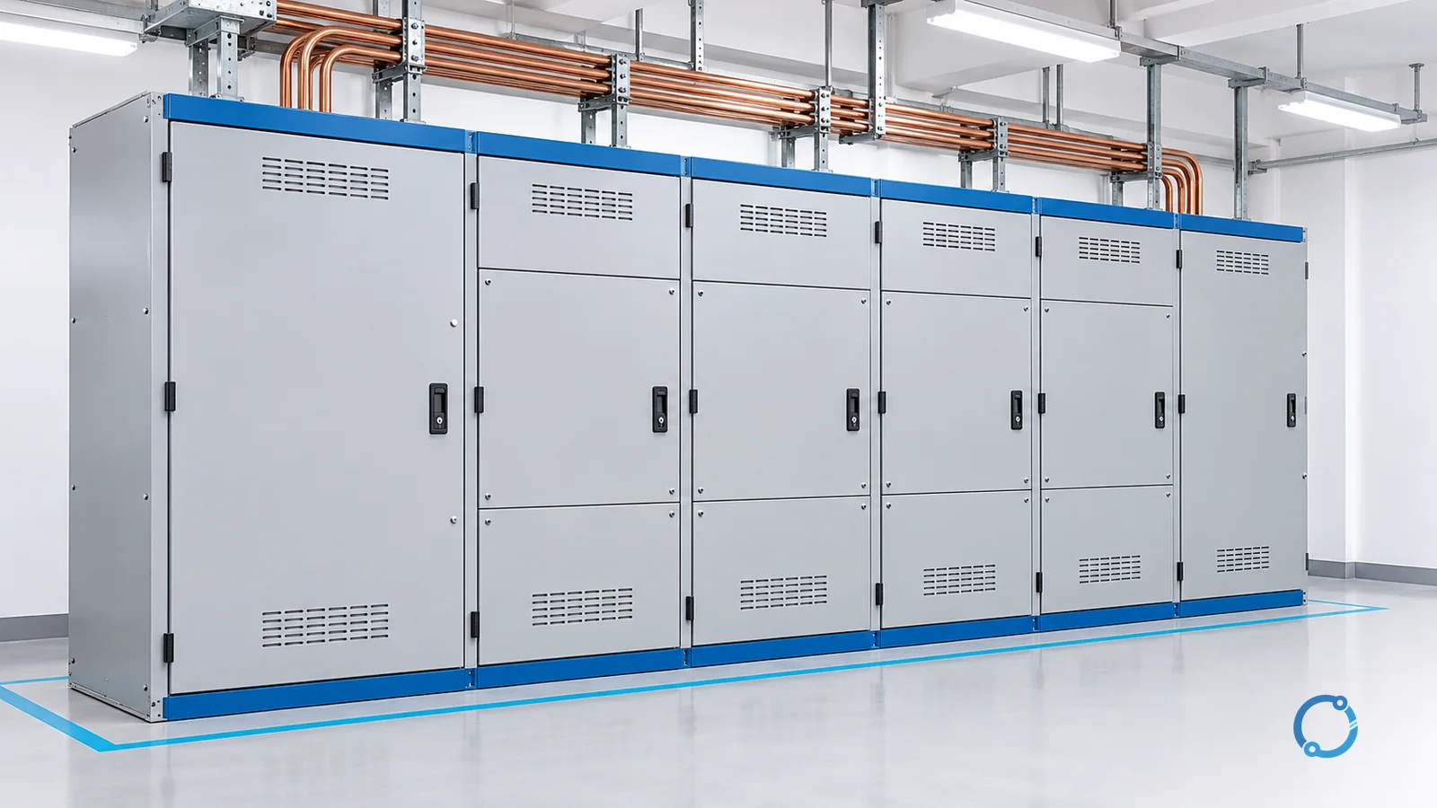
Short answer: Switchgear is an assembly of switching, protective, control and measuring equipment used to control, protect and isolate electrical circuits and equipment. Its functional map is switch / protect / isolate / control & meter. A circuit breaker may be one component inside that assembly; the complete switchgear also provides the electrical paths, interfaces and supporting structure that let those functions work together.
Think of a distribution point where incoming power must reach several outgoing circuits. Operators need a way to connect or disconnect a circuit, protection needs a way to interrupt a fault, and maintenance needs an established isolation boundary. Measurement and control provide the information and commands connecting those tasks. Switchgear organizes these roles around the power circuit.
This overview explains the assembly, the components and the language used to describe it. It does not specify a product, prescribe a switching sequence or establish permission to work on energized equipment.
Four functions, with different jobs
Switch: establish or interrupt a power path
Switching changes the state of an electrical circuit. A feeder may be connected to supply a load or disconnected when its service is not required. Depending on the device and its declared capability, switching may involve normal load current, no-load conditions or fault interruption.
Those duties are different. A component that provides an open position is not automatically capable of interrupting load current or a short circuit. The assembly’s internal arrangement must assign each duty to equipment designed for it; the word “switch” alone does not establish interruption capability.
For a reader tracing a diagram, the useful question is: which device changes the power path, and under what electrical conditions can it do so? That gives more information than treating every movable contact as equivalent.
Protect: detect an abnormal condition and clear it
Protection responds to defined abnormal conditions. A protective relay may receive current or voltage signals, decide that a fault criterion has been met and send a trip command to a breaker. A fuse instead combines its current-sensitive response and interruption action within its own operating principle.
Protection therefore includes both a decision and an action. A relay that identifies a fault does not itself interrupt the main power circuit. A breaker needs an appropriate release or trip arrangement to open when required. Reading those parts as one chain explains why switchgear contains control wiring as well as large power conductors.
The purpose is to remove the affected circuit under the scheme’s design conditions, rather than disconnecting unrelated circuits indiscriminately. This overview does not determine fault settings, selectivity or interrupting ratings.
Isolate: establish an electrical separation boundary
Isolation provides the separation needed for a defined safety boundary. A disconnector, an isolating arrangement or a withdrawable assembly may contribute to that function when used within its declared design and the site’s procedure.
An open breaker indication is not, by itself, proof that equipment is safe to touch. Other supplies, stored energy and the actual isolation arrangement still matter. Qualified personnel establish and verify the work condition under the applicable safety rules.
Isolation is thus a different question from whether current normally flows. The relevant question is whether the required separation has been established, secured and verified for the intended work, rather than whether a display currently reads zero.
Control and meter: command, observe and interpret
Control provides commands and permitted operating relationships. Local controls, remote interfaces, interlocks and auxiliary circuits can determine how devices are allowed to change state. Metering and indication provide information such as current, voltage and device position.
A control command is a request to act; a position indication is a reported state; a measurement describes an electrical condition. They should not be confused. For example, a trip command does not alone prove that the main contacts opened, and an open-position indication does not constitute verification of absence of voltage.
Together these functions let operators and protection systems understand and manage the power path. Their exact implementation varies with the assembly and installation, without changing the basic division of jobs.
Components: what each part contributes
The following map describes roles, not a mandatory bill of materials. Some assemblies combine functions in one device, and not every installation contains every component listed.
| Component | Role in the assembly |
|---|---|
| Circuit breaker | Makes, carries and interrupts current within its declared duties, including specified fault interruption. |
| Disconnector or isolating switch | Provides an isolating function under its specified conditions; fault interruption must not be assumed. |
| Earthing switch | Connects an isolated part of the circuit to earth as part of a designed safety arrangement. |
| Busbars | Form the common conductive path distributing power between incoming and outgoing circuits. |
| Current transformer | Provides a scaled current signal for appropriate measuring or protective circuits. |
| Voltage transformer | Provides a scaled voltage signal for appropriate measuring or protective circuits. |
| Protective relay | Evaluates measured quantities and issues commands according to its protection functions. |
| Fuse | Interrupts current through its current-responsive operating element within its declared capability. |
Follow the power path and the information path separately
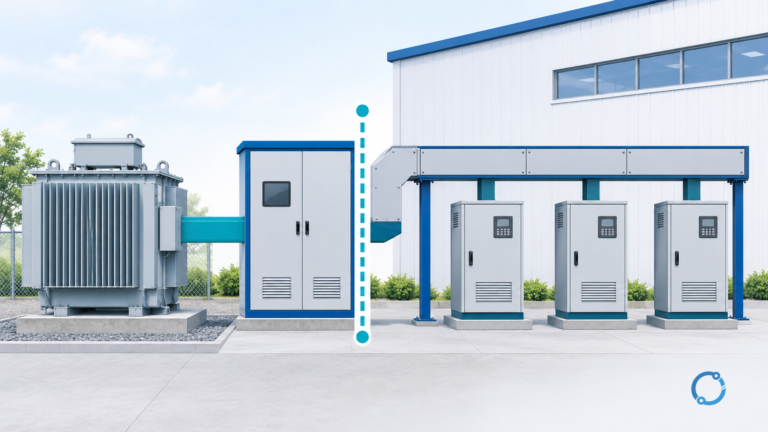
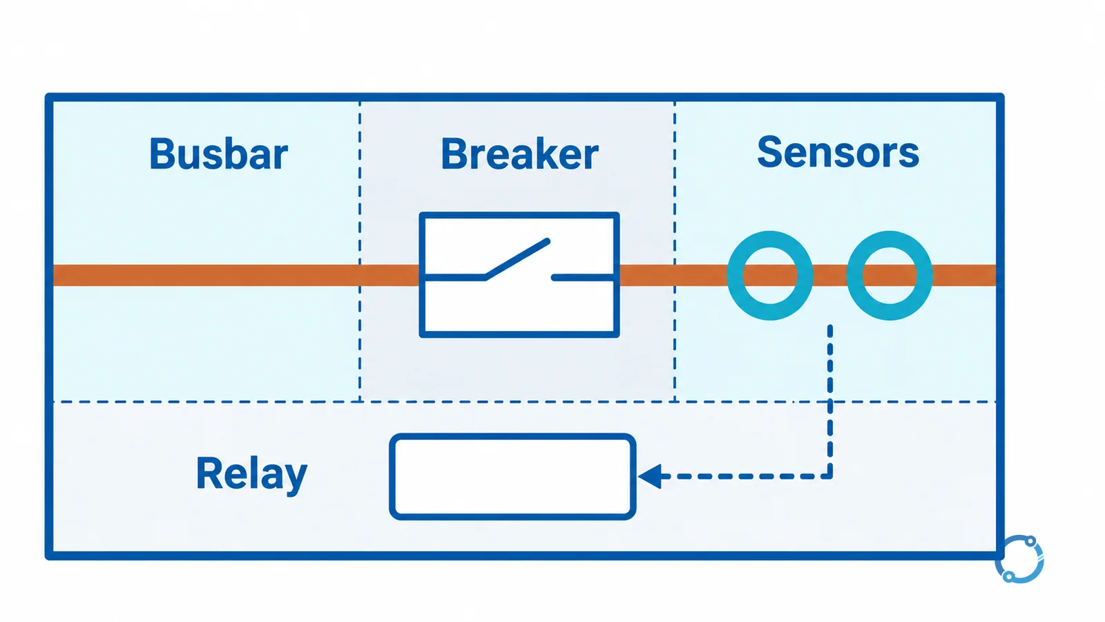
The main power path may run from an incoming connection through a switching device onto a busbar and then through outgoing devices to loads. That path carries the energy being distributed. Bus supports, insulation, connections and the enclosure provide the physical and electrical environment around it.
The information path starts with sensors or instrument transformers, continues through relay or metering functions and reaches indication, control or trip circuits. Its purpose is to represent conditions and request actions. A small control circuit can command a large breaker without carrying the main circuit’s current.
Keeping those paths separate in your mental model makes a crowded panel easier to understand. The breaker is the actuator in one chain, the relay is a decision element in another, and the busbar is the shared energy path. Their enclosure brings them together without making their jobs interchangeable.
The dedicated overview of medium-voltage switchgear switching devices explains those device distinctions in more depth.
Voltage classes: LV, MV and HV boundaries
For this article’s AC overview, use the following distribution-oriented grouping:
| Overview label | Rated-voltage band used here | Boundary interpretation |
|---|---|---|
| Low voltage, LV | 1 kV and below | Exactly 1 kV remains in this LV band. |
| Medium voltage, MV | Above 1 kV through 52 kV | Exactly 52 kV remains in this MV band. |
| High voltage, HV | Above 52 kV | This is the upper overview band, not the full IEC meaning of “high-voltage.” |
Important standards distinction: IEC 62271-1 uses “high-voltage” for switchgear rated above 1 kV, so its high-voltage scope also includes what distribution engineers commonly call MV. The table is a useful three-band vocabulary map; it must not be presented as three mutually exclusive formal definitions imposed by IEC 62271-1.
The official IEC 62271-1:2017+AMD1:2021 scope confirms that its AC switchgear scope begins above 1000 V. The IEC 62271-200 catalogue identifies AC metal-enclosed equipment above 1 kV through 52 kV while retaining “high-voltage” in the standard’s title. That apparent mismatch disappears once the difference between standard scope and common MV terminology is understood.
The low-voltage assembly family is addressed by IEC 61439, rather than by assuming that every assembly belongs to IEC 62271. The BSI scope summary for IEC 61439-1 identifies the AC assembly limit of 1000 V. DC uses a different voltage scope and is outside this AC table.
What the voltage label does not tell you
A voltage band does not establish the assembly’s fault duty, insulation performance, continuous-current capability or suitability for a particular environment. Those are separate declared characteristics and verification questions. Two assemblies in the same voltage band can have different functions and operating limits.
Also distinguish the system’s nominal voltage from an equipment rated-voltage designation. A voltage-class heading is an orientation aid, not a substitute for the actual equipment documentation and applicable standards. This page deliberately avoids assigning invented typical application values to the three bands.
Common forms: enclosure and movement are separate descriptions
Metal-enclosed and metal-clad
Metal-enclosed broadly describes an assembly enclosed by metal, while metal-clad describes a more specific compartmentalized construction within its applicable standards framework; the terms should not be interpreted without identifying that framework. A metal case alone does not establish the segregation, accessibility or protection characteristics implied by a particular metal-clad designation. The focused metal-clad vs metal-enclosed MV switchgear comparison develops those distinctions rather than treating the words as a universal quality ranking.
Fixed and withdrawable
Fixed equipment remains installed in its normal mounted position, whereas withdrawable arrangements allow a designated functional unit to move between defined positions within the assembly design. Withdrawability changes the connection and access arrangement; it does not automatically establish a safe work condition or eliminate the need for verification. The separate fixed vs withdrawable MV switchgear guide explains that construction choice without assuming it is the same question as enclosure classification.
Switchgear, switchboard, MCC and panelboard
These terms describe overlapping electrical assemblies whose formal boundaries depend on jurisdiction, product standards and construction. Their names are useful orientation, but their functions and declared assembly standards should settle a technical classification.
- Switchgear: emphasizes an assembly’s coordinated switching, protection, isolation and control functions around power circuits.
- Switchboard: commonly describes a distribution assembly carrying switches, protective devices and related equipment; its formal distinction from switchgear depends on the applicable product standard.
- Motor control center (MCC): organizes motor-related power and control units around a common distribution arrangement; see MCC selection for mechanical loads for that application-specific task.
- Panelboard: generally describes a distribution assembly supplying branch circuits through their protective devices, within its applicable enclosure and product-standard definition.
A useful first distinction is the primary circuit task: controlling motor feeders is different from distributing branch circuits, even though both assemblies can contain breakers and busbars. Conversely, two cabinets serving a similar distribution task may still belong to different product-standard categories.
Do not classify equipment from cabinet size, paint color or its location in a building. A description on a drawing, the assembly designation and the applicable standard provide a more reliable boundary than appearance alone. This prevents a familiar-looking enclosure from being assigned interruption or isolation capabilities it has never claimed.
Where switchgear sits in the electricity system
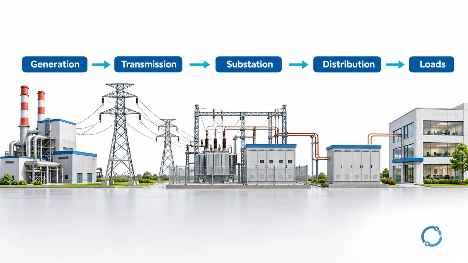
The simplified energy chain is:
Generation -> Transmission -> Substation -> Distribution -> Loads
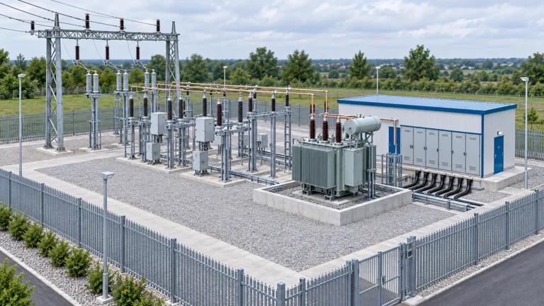
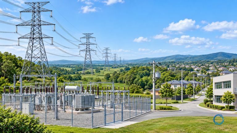
Switchgear appears at substations and distribution points to manage connections between sources, transformers, bus sections and outgoing circuits. It can also appear at generating facilities and other system interfaces; its role is not limited to the two locations highlighted in the teaching diagram.
At a substation, the assembly helps organize the paths into and out of a bus or transformer connection. In distribution, it helps divide incoming power into controlled outgoing circuits. The voltage may change elsewhere in the chain through transformers, but switchgear’s fundamental job remains managing and protecting the circuit paths.
Read a system diagram by asking four questions
First, find the source and outgoing circuits so that the energy path is clear. Second, identify which devices establish or interrupt each path. Third, locate the protective decision and trip functions. Fourth, distinguish the documented isolation boundary from indications that merely report an operating state.
Those questions use the same four-function map as the opening definition. They help explain what the assembly does without turning an overview into a selection worksheet or maintenance procedure. If a drawing cannot answer one of them, the missing information belongs in the relevant design or operating documentation.
Where the overview ends
Putting equipment into service is a separate controlled task covered by MV switchgear commissioning and release. Decisions about continued service, repair, retrofit or replacement belong in aging switchgear assessment.
Operating heat and its interpretation are addressed in LV switchgear operating temperature, rather than inferred from the assembly’s voltage label. These specialist subjects depend on evidence beyond the definitions and system relationships explained here.
FAQ
What is switchgear in simple terms?
Switchgear is an assembly that switches, protects, isolates, controls and measures electrical circuits. It combines power-circuit devices with the supporting conductors, structure and control interfaces needed for those functions. A breaker can be one part of the assembly.
What are the main components of switchgear?
Common components include circuit breakers, disconnectors, earthing switches, busbars, instrument transformers, protective relays and fuses. The exact combination depends on the assembly. These devices have different roles and are not automatically interchangeable.
What are the LV, MV and HV boundaries used in this article?
For this AC overview, LV is 1 kV and below, MV is above 1 kV through 52 kV, and the upper HV band is above 52 kV. IEC 62271-1 also uses high-voltage as an umbrella term for switchgear above 1 kV, including the common MV band.
Is switchgear the same as a motor control center?
Not exactly. An MCC organizes motor power and control units, while switchgear is a broader assembly description centered on switching, protection, isolation and associated control functions. Formal product classifications depend on the applicable standards and construction.
Does an open breaker mean switchgear is safe to work on?
No. An open indication alone does not establish a verified safe work condition. Qualified personnel must address isolation, other possible supplies, stored energy and the required verification under the applicable procedure before work begins.