Short answer
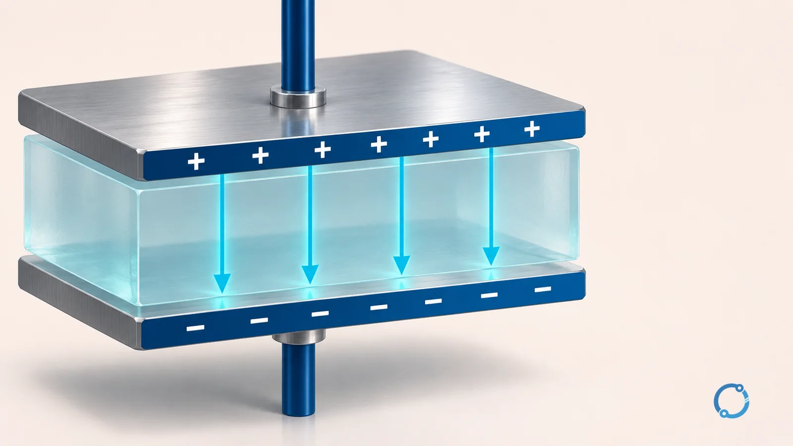
A capacitor is a passive electrical component made from two conductors separated by an insulating material called a dielectric. It stores separated charge and electric-field energy. Unlike a battery, it does not create energy through a chemical reaction: it holds energy temporarily in the electric field between its plates.
The amount of charge stored for a given voltage is its capacitance. That simple relationship explains why a capacitor opposes a change in voltage, why it draws current while charging or discharging, and why its opposition to alternating current depends on frequency.
Two conductors and a dielectric
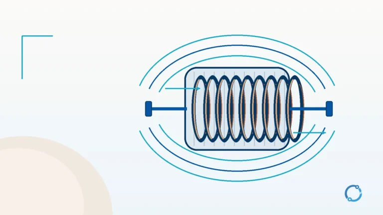
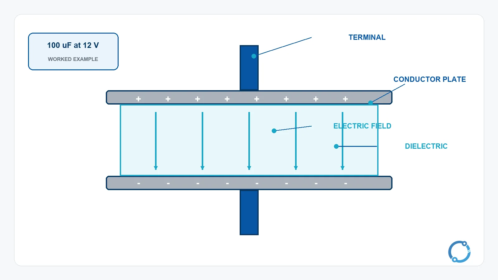
The basic parallel-plate capacitor has two conductive plates and a dielectric between them. One plate accumulates positive charge while the other accumulates negative charge when a voltage is applied. The dielectric prevents steady conduction between the plates, but it is affected by the electric field and stores energy.
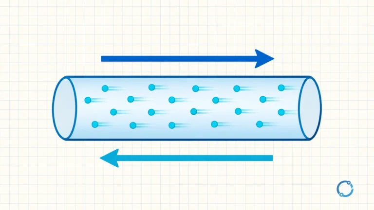
Real capacitors use many constructions: rolled metalized film, ceramic discs, multilayer ceramic chips, electrolytic foil and other arrangements. The geometry may not look like two flat plates, but the electrical model still contains conductors, an insulating region and terminals. The electric current explanation is useful here because the charging current is a movement of charge, not a flow of charge through the dielectric.
The material between the plates matters. A dielectric with greater permittivity increases capacitance for the same geometry, and a thinner dielectric usually increases capacitance. The simplified relation is:
C = epsilon x A / d
Here C is capacitance, epsilon is the permittivity of the dielectric, A is the effective plate area and d is the separation. This is a design relationship, not a permission to exceed a capacitor’s rated voltage. A thinner dielectric may increase capacitance, but it also reduces the breakdown margin.
Capacitance is charge divided by voltage
Capacitance is defined as:
C = Q / V
where Q is the charge in coulombs, V is the voltage in volts and C is the capacitance in farads. A one-farad capacitor stores one coulomb when one volt is applied, under the ideal definition. The farad is a large unit for many electronic circuits, so submultiples are common:
| Unit | Relationship to the farad |
|---|---|
| millifarad (mF) | 1 mF = 0.001 F |
| microfarad (uF) | 1 uF = 0.000001 F |
| nanofarad (nF) | 1 nF = 0.000000001 F |
| picofarad (pF) | 1 pF = 0.000000000001 F |
The article uses uF in plain text for readability; equipment markings commonly use the micro sign. Always check the marking, the datasheet and the circuit context rather than assuming that a code means one exact value.
Worked example: charge and stored energy
Take a 100 uF capacitor charged to 12 V. Convert microfarads to farads before substituting:
100 uF = 100 x 10^-6 F = 0.000100 F
The stored charge is:
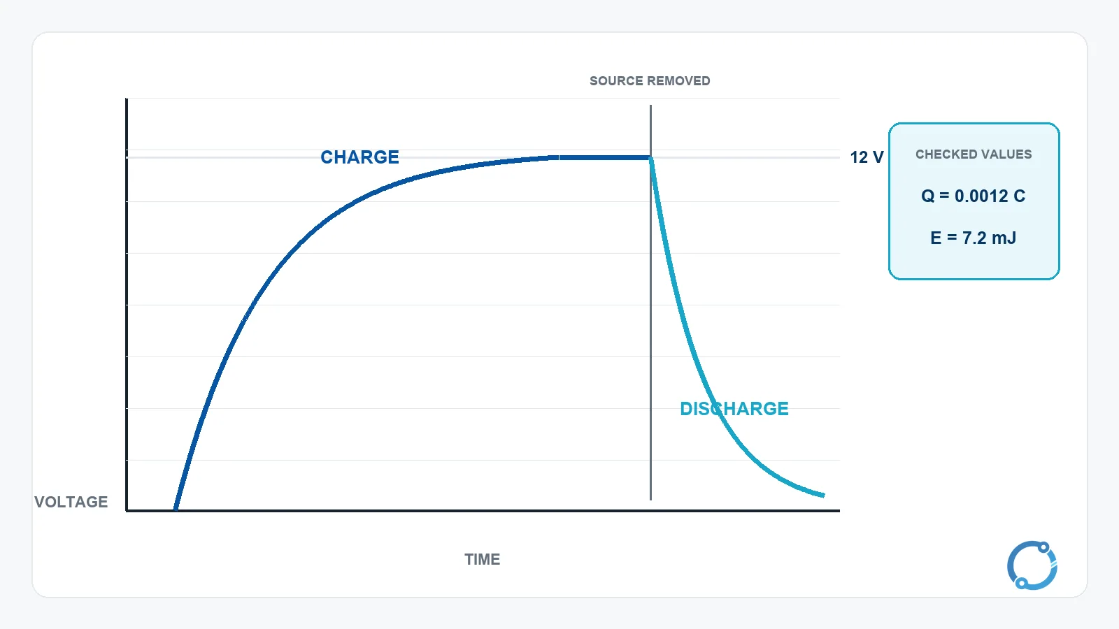
Q = C x V = 0.000100 F x 12 V = 0.0012 C
The energy stored in the ideal capacitor is:
E = 1/2 x C x V^2
E = 0.5 x 0.000100 F x (12 V)^2 = 0.0072 J
That is 7.2 mJ. The example shows why a capacitor can be important for short bursts of energy even when its total stored energy is small compared with a battery. It also shows why voltage matters so much: energy rises with the square of voltage.
Why the voltage cannot change instantly
The electric field is produced by separated charge. Changing the voltage means changing that stored charge distribution. The capacitor resists this change because the charge on each plate attracts the opposite charge on the other plate. An external circuit can supply or remove charge, but it cannot do so without current and time.
In the ideal model, the voltage across a capacitor is continuous unless an infinite current were available. That is why a capacitor can suppress a fast voltage transient and why an uncharged capacitor acts temporarily like a low impedance when a voltage step is first applied. The current is limited by the rest of the circuit, not by a resistor inside an ideal capacitor.
This model has a practical limit. A real capacitor has equivalent series resistance (ESR), equivalent series inductance (ESL), dielectric loss and a maximum current rating. A very fast edge can produce a large current through a physically small part, and the resulting heating or voltage overshoot may exceed the component’s capability. The ideal statement that voltage cannot change instantly is a starting point, not a complete transient model.
Charging and discharging
When a DC source is connected through a resistance, the capacitor starts with zero voltage and draws a relatively large charging current. As charge accumulates, the capacitor voltage rises and the voltage across the resistor falls, so the current decreases. In the ideal model, the current approaches zero as the capacitor voltage approaches the source voltage.
That does not mean the dielectric suddenly becomes a conductor. It means the change in voltage has become small enough that the capacitor is no longer accepting much additional charge. The capacitor opposes a change in voltage because the stored charge creates an electric field that resists further change.
When the source is removed and a load is connected across the plates, the stored charge can drive current through the load in the opposite direction. The capacitor voltage falls as the field energy is released. The discharge current depends on the load and the capacitance, and can be hazardous even after the main supply is disconnected.
The product of resistance and capacitance gives the RC time constant:
tau = R x C
The time constant is a characteristic response time, not a universal delay setting. In a simple RC circuit, the capacitor approaches its final voltage gradually and is practically close to the final state after several time constants. The exact response still depends on the circuit and its tolerances.
AC behaviour and capacitive reactance
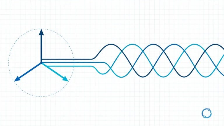
In an AC circuit, the applied voltage changes continuously. The capacitor therefore charges and discharges repeatedly. For an ideal sinusoidal capacitor, the current leads the voltage by 90 electrical degrees, and the opposition to current is called capacitive reactance:
Xc = 1 / (2 x pi x f x C)
Here Xc is reactance in ohms, f is frequency in hertz and C is capacitance in farads. For 10 uF at 50 Hz:
C = 10 x 10^-6 F
Xc = 1 / (2 x pi x 50 x 10 x 10^-6)
Xc = 318.3 ohm, approximately 318 ohm.
The inverse relationship is useful: increasing frequency or capacitance reduces reactance. A capacitor therefore behaves differently at 50 Hz, 60 Hz and high switching frequencies. The ideal 90-degree phase relationship is a useful starting point, but a real capacitor also has equivalent series resistance and inductance, dielectric loss and voltage-dependent behavior.
Capacitors are widely used in power-factor correction because they can supply reactive power locally near a load. The power-factor guide explains the difference between active, reactive and apparent power, while the capacitor bank functional diagram shows how switching and control fit around a bank. A capacitor does not create active power; it changes the timing between voltage and current and can reduce the reactive-power demand seen by the supply.
Series and parallel rules
Capacitors combine in the opposite way to resistors. Capacitors in parallel have the same voltage across each branch, and their capacitances add:
C_parallel = C1 + C2 + C3 + ...
For example, 10 uF in parallel with 22 uF gives:
10 uF + 22 uF = 32 uF
Capacitors in series share the same charge in the ideal case, and the reciprocal of the total capacitance is the sum of the reciprocals:
1 / C_series = 1 / C1 + 1 / C2 + 1 / C3 + ...
For two identical 10 uF capacitors in series:
1 / C_total = 1 / 10 + 1 / 10 = 2 / 10
C_total = 5 uF
The voltage across series capacitors must also be checked. In practice, leakage, tolerance and the initial charge can make the sharing unequal, so series connection may require balancing provisions. The series and parallel circuits guide provides the underlying voltage and current reasoning.
How a capacitor differs from a battery
A battery stores chemical energy and converts it through electrochemical reactions. Its voltage is set mainly by the chemistry and the state of charge, and it can supply energy for a relatively long period. A capacitor stores energy in an electric field and can release it much more quickly, but its voltage falls steadily as that stored energy is drawn down.
A capacitor is often used to supply a short pulse, smooth a fluctuating voltage or provide a local path for high-frequency current. A battery is usually chosen for sustained energy storage. The distinction is useful because a capacitor and a battery can look similar in a block diagram: both store energy and both have voltage across their terminals. Their internal mechanisms, voltage behavior and safety requirements are different.
Some applications combine both. A battery may provide the long-term energy, while a capacitor handles a short high-current demand or decouples fast disturbances. The design still has to account for the capacitor’s voltage rating, ESR, ripple current and stored-charge hazard.
Common capacitor types
| Type | Basic construction | Typical role |
|---|---|---|
| Ceramic | Ceramic dielectric with conductive electrodes in several possible geometries | Decoupling, coupling, filtering and small-signal tuning |
| Film | Polymer film dielectric, often metalized | Filtering, coupling, pulse and AC applications |
| Aluminium electrolytic | Metal foil and an oxide dielectric with an electrolyte; many types are polarized | Energy buffering and smoothing where high capacitance is useful |
| Supercapacitor | High-surface-area electrodes and an electric double layer | Short-term energy storage and rapid charge/discharge buffering |
These are broad families, not guarantees of a particular voltage, capacitance, ripple rating or lifetime. A ceramic capacitor with a small package is not automatically interchangeable with another ceramic part, because dielectric class, tolerance and voltage coefficient can differ. The type name describes construction and broad behavior, not a complete specification.
For fixed capacitors used in electronic equipment, IEC 60384-1:2021 is a generic specification covering terms, inspection procedures and test methods within its scope. A standard’s existence does not prove that a particular capacitor is compliant. The datasheet and the qualified component approval remain the application evidence.
Reading the datasheet
The nominal capacitance is only one line of a capacitor specification. A practical selection also checks tolerance, rated voltage, temperature range, ESR, ripple-current capability and the behavior of the dielectric under the actual operating conditions. For power circuits, the permissible ripple current may be more limiting than the capacitance value. For timing circuits, tolerance and temperature drift may dominate. For high-voltage circuits, insulation and transient capability become central.
The datasheet also identifies polarity where it exists, the permitted mounting direction, soldering conditions and any derating rules. A part that is suitable for a low-voltage signal filter may be unsuitable for a pulse application with a high rate of voltage change. The application note and the qualified component approval are more useful than a generic “best capacitor type” claim.
When a capacitor is used in a power-factor-correction bank, the relevant design also includes switching, discharge resistors, fusing, ventilation and control. The capacitor bank functional diagram shows the system context. A single capacitor’s capacitance value does not describe the whole bank or its switching duty.
Rated voltage and stored-charge safety
The rated voltage is a limit tied to the dielectric system, construction and permitted operating conditions. Exceeding it can cause breakdown, permanent damage, leakage or an unsafe failure. A capacitor may also see repetitive pulses, ripple current and transients that are not captured by its nominal DC voltage alone.
Many aluminium electrolytic capacitor types are polarized. Reverse voltage can damage the dielectric and may lead to venting or other failure. Non-polarized capacitors do not automatically tolerate every AC or pulse condition, either. Use the manufacturer’s polarity, ripple, temperature and voltage rules for the actual part.
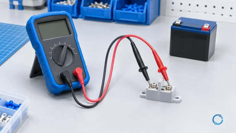
A capacitor can retain charge after the supply is switched off. Before service, the stored energy must be discharged using an approved method and the result verified with a suitable meter. Large power-factor-correction capacitors and DC-link capacitors need particular care. This is a qualified-person task governed by the site’s isolation, discharge and verification procedure.
The microfarad-to-kvar conversion guide explains a calculation used in power-factor work. The why raise power factor article explains the system-level reason for correction. Neither calculation makes a capacitor safe to touch or removes the need for a discharge procedure.
Where capacitors appear
Capacitors are used for coupling, decoupling, filtering, timing, energy buffering, motor starting, power-factor correction and many other functions. In each case, the construction and dielectric must suit the job. A capacitor that is excellent for small-signal timing is not necessarily suitable for a high-ripple power converter.
The useful question is not “what is the biggest capacitor?” but “what energy, voltage, ripple, tolerance, temperature and reliability requirement does this circuit impose?” The answer can change the type, the package, the series or parallel arrangement and the protection around it.
Frequently asked questions
Does a capacitor store electricity?
It stores separated charge and electric-field energy. The plates hold opposite charges, and the dielectric supports the electric field. It is not a chemical energy store in the same sense as a battery.
Does a capacitor block DC?
In the ideal steady state, a capacitor does not sustain a conduction current through its dielectric. It does draw current while charging or discharging, so an uncharged capacitor is not an open circuit at the instant voltage is applied.
Why does current lead voltage in a capacitor?
The capacitor current depends on the rate of change of voltage. In the ideal sinusoidal model, this produces a 90-degree phase lead. Real capacitors include equivalent resistance and inductance, so the actual phase relationship is not perfectly 90 degrees.
Is a larger capacitance always better?
No. Larger capacitance can store more charge at a given voltage, but it can also increase inrush current, physical size, cost and discharge energy. The correct value depends on the required time constant, ripple, filtering frequency and source behavior.
Can capacitors be connected in series for higher voltage?
They can be connected in series in some designs, but the voltage sharing must be controlled and the arrangement must be qualified for the capacitor family. Do not assume that two identical parts automatically divide voltage equally in service.