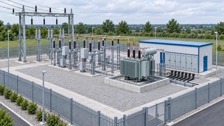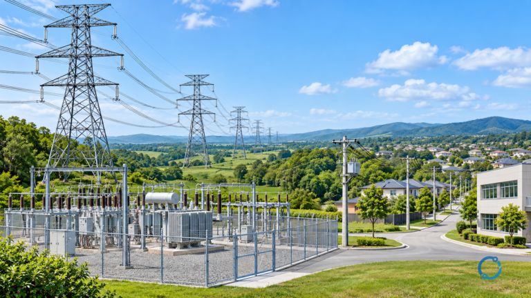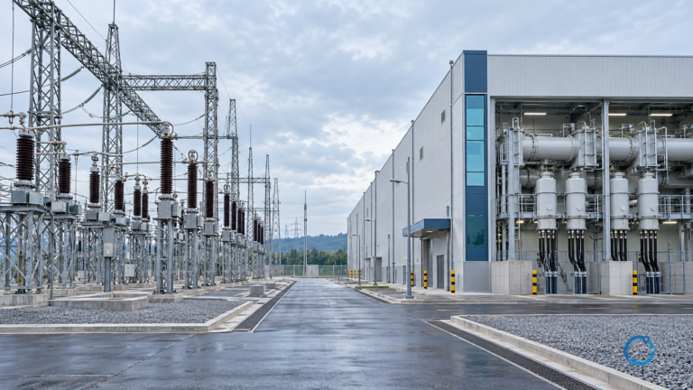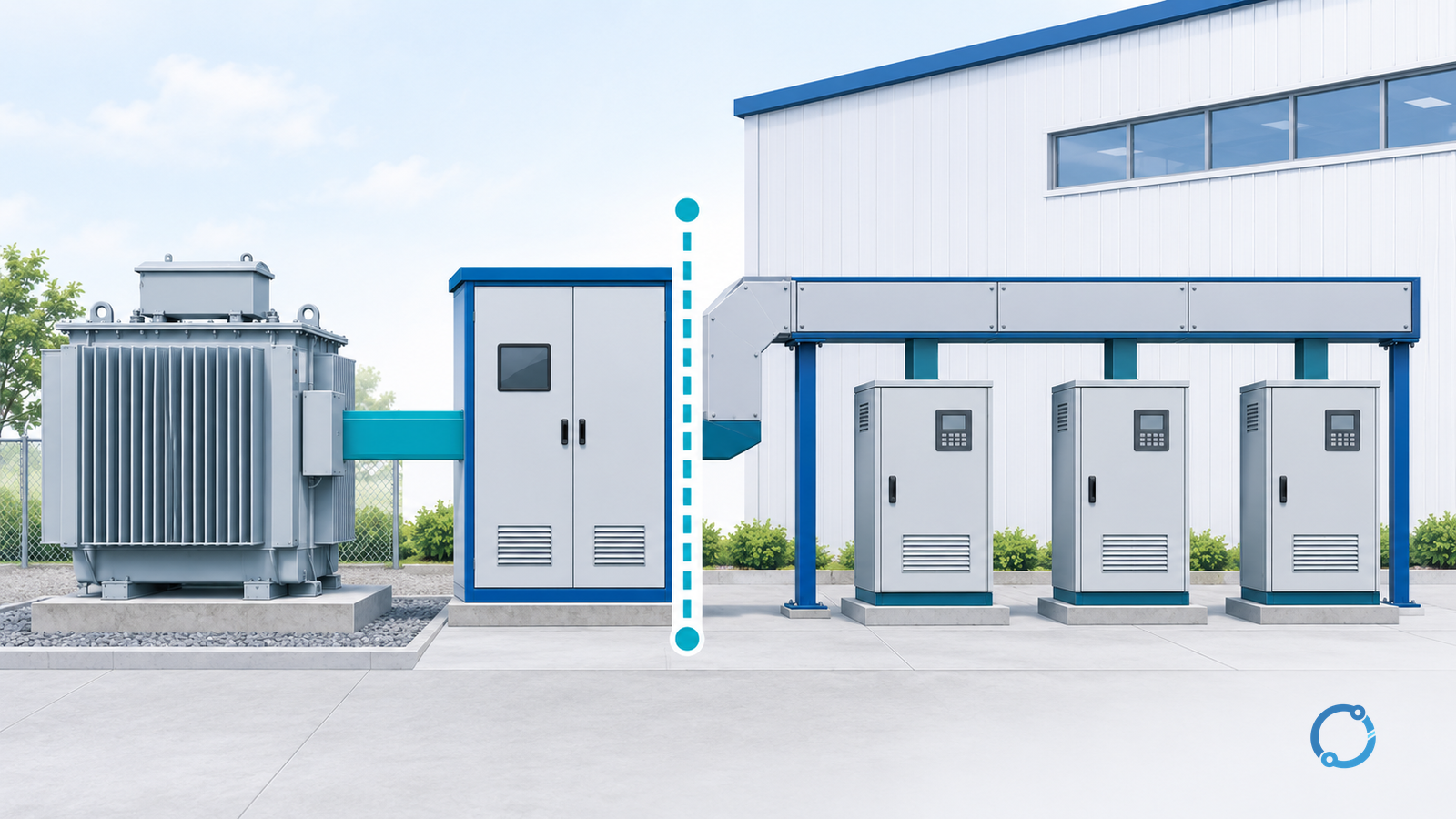
IEEE 519 harmonic control is a point-of-common-coupling (PCC) question before it is a percentage question. The official IEEE SA catalog says the active 2022 standard establishes steady-state waveform-distortion goals at the interface between source and load, described as the PCC. Its P519 scope states that voltage and current distortion limits apply at the user PCC to the overall installation containing harmonic-producing loads.
That means a total harmonic distortion (THD) value printed by a drive, meter or power-quality analyzer at an equipment terminal is not automatically an IEEE 519 compliance result. The measurement location, denominator, load condition, edition and steady-state window must be stated first.
What the PCC means in this standard
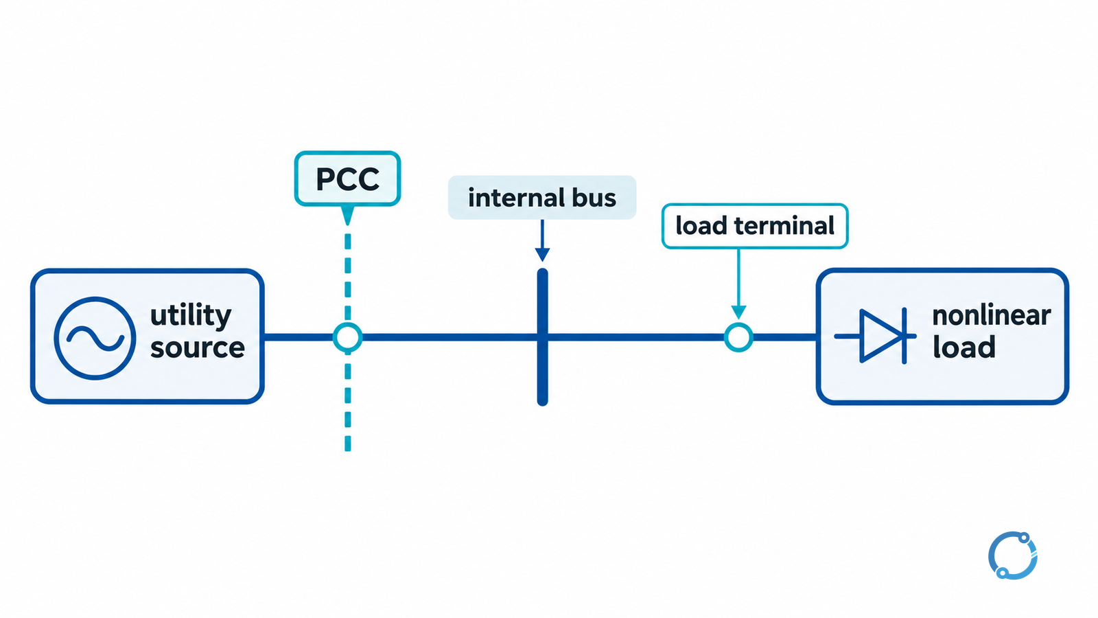
IEEE 519-2022 describes the PCC as the interface between sources and loads. The standard’s public catalog text says its design goals are intended to reduce interference between electrical equipment and to set the power quality provided at the PCC. The IEEE SA catalog identifies the user PCC as the point where the standard’s steady-state limits apply. An equipment terminal is therefore a different boundary, not an automatic substitute for that PCC.
In practical reporting, identify the PCC from the utility interconnection and facility one-line information instead of choosing the most convenient measurement point. A load terminal, a distribution board inside a plant, and the utility-user interface can show different harmonic voltages and currents because supply impedance and load current differ.
THD vs TDD
| Metric | Definition | Denominator | Main reporting risk |
|---|---|---|---|
| Voltage THD | RMS of harmonic voltage components divided by RMS fundamental voltage | Fundamental voltage at the measurement point | A light-load reading can look large or unstable when the denominator changes |
| Current THD | RMS of harmonic current components divided by RMS fundamental current | Fundamental current at the measurement point | A lightly loaded nonlinear load can produce a high percentage even when harmonic amperes are modest |
| Current TDD | RMS harmonic current divided by maximum demand load current at the PCC | Maximum demand load current, not instantaneous fundamental current | Using the wrong demand-current value or applying it away from the PCC |
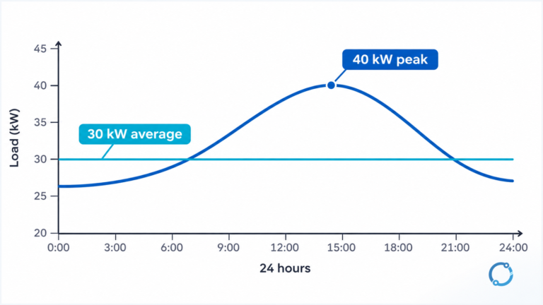
The IEEE Technology Navigator defines THD as the ratio of the RMS of harmonic components to the RMS fundamental. For current, it says the formula applied to the first 50 harmonic orders is the definition embedded in IEEE Std 519-2022. It also explains that TDD replaces the fundamental-current denominator with maximum demand load current at the PCC, giving a more stable benchmark when fundamental current varies widely with load.
Written as equations:
THD = sqrt(I2² + I3² + ... + In²) / I1
TDD = sqrt(I2² + I3² + ... + In²) / IL
Here I1 is fundamental current RMS and IL is maximum demand load current at the PCC. The same structure applies to voltage THD when voltage harmonic RMS values and fundamental voltage are used. These definitions are not substitute values for the standard’s limit tables.
Edition and scope boundaries
The IEEE SA catalog identifies IEEE 519-2022 as active, approved by the IEEE SA Standards Board on 13 May 2022 and published 5 August 2022. It supersedes IEEE 519-2014. The catalog says the standard addresses steady-state limitations, that transient conditions exceeding the limits may be encountered, and that radio-frequency interference is not covered.
References to older editions may still appear in project documents and legacy reports. The IEEE SA catalog identifies IEEE 519-2022 as active and IEEE 519-2014 as superseded, but a project can still be governed by an edition adopted in its contract or by the applicable authority. Check the adopted edition, then read its limit tables in that standard. This article does not reproduce numerical limits from an inaccessible full text or from a search snippet.
IEEE’s harmonic-distortion explainer says nonlinear loads generate components at integer multiples of the fundamental frequency and describes the characteristic 5th, 7th, 11th and 13th current harmonics from six-pulse conversion. A twelve-pulse arrangement is described as cancelling the 5th and 7th, leaving the 11th and 13th as the lowest significant orders. Those are mechanism examples, not a filter-sizing method or a guarantee about a real installation.
Reading a harmonic report
A useful report should make the following checks possible:
- Edition: which IEEE 519 edition the report claims, and whether the local contract or regulator adopts a different edition.
- PCC: the exact physical and one-line location where the standard’s limits are applied.
- Voltage class: the bus voltage at the PCC, with units and measurement basis.
- Metric: voltage THD, individual harmonics, current THD or current TDD; do not label every percentage
THD. - Denominator: measured fundamental RMS or maximum demand load current at the PCC for TDD.
- Demand current: the value, period and source of
IL, including how maximum demand was established. - Harmonic orders: which orders were included and the measurement method’s bandwidth.
- Observation window: steady-state averaging or statistical window, with season, operating schedule and load state.
- Load state: which nonlinear loads were operating and whether inverter-based resources are present.
- Responsibility: utility or system-owner voltage-quality information versus the user’s current-distortion information.
- Limitations: transients, interharmonics, radio-frequency interference and equipment-internal harmonics that the standard scope does not settle.
If a report gives only THD = 4.8% with no location, denominator, load state or edition, it does not answer the IEEE 519 question. Ask for the PCC one-line, the measurement setup and the edition-specific limit basis before drawing a compliance conclusion.
What this page does not decide
IEEE 519 is a system-interface standard, not a product certification or a filter-selection chart. It does not tell a reader which reactor, active filter or drive topology to buy, and it does not prove that a device complies merely because a category is mentioned in the standard. Equipment emission standards, interconnection rules and utility contracts can impose different boundaries.
For the next engineering question—choosing mitigation from spectrum, PCC and load conditions—see OHELE’s VFD harmonic mitigation guide. A measurement plan also needs instrument class, sampling and duration; the power-quality monitoring guide covers that separate task.