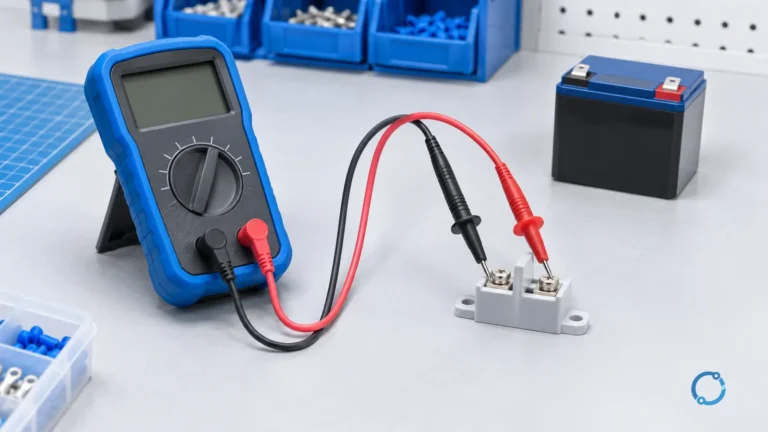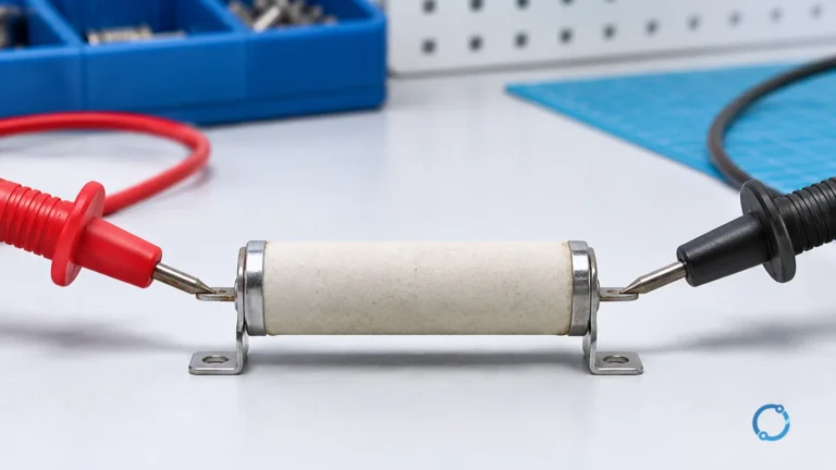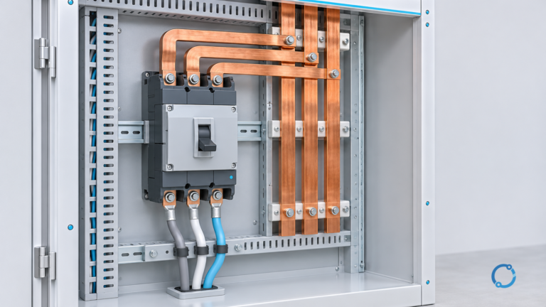
Voltage drop is the reduction in voltage along a conductor path while current flows. For a simplified resistance-only estimate, calculate the conductor resistance first, apply the path factor for the circuit arrangement, and compare the resulting volts with the source voltage:
R = rho L / A
Vdrop = 2 I R for a single-phase path
Vdrop = sqrt(3) I R for a balanced three-phase path
Vdrop (%) = Vdrop / Vsource x 100
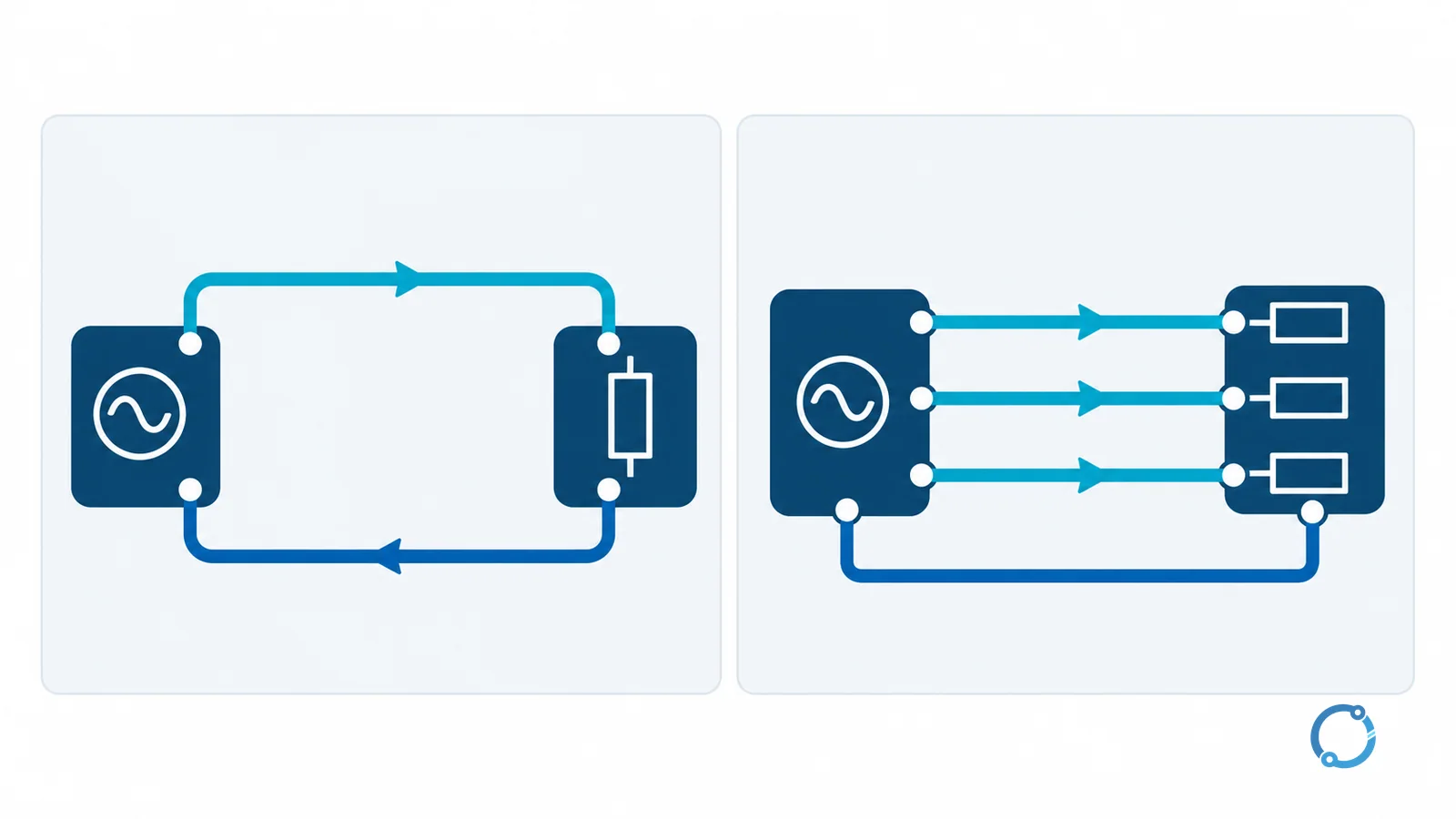
The factor of 2 in the single-phase expression accounts for the outward and return conductors. The sqrt(3) factor applies to the simplified balanced three-phase line-to-line model. These equations are useful teaching and preliminary-estimation tools; they are not a complete cable-sizing method.
Formula and input table
| Symbol | Meaning | Unit | Point to verify |
|---|---|---|---|
rho |
Volume resistivity of the conductor material | ohm metre | Material, temperature basis, and whether the value is for the actual conductor |
L |
One-way conductor length | metre | Do not enter the total loop length twice; the path factor handles the return |
A |
Conductor cross-sectional area | square metre | Convert mm2 to m2 before substituting |
I |
Current in the conductor | ampere | Use the design current and state whether it is balanced |
R |
Resistance of one conductor over length L |
ohm | This simplified model uses resistance, not AC impedance |
Vsource |
Voltage used as the percentage base | volt | For three-phase, use the stated line-to-line base consistently |
For the examples below, use conventional 20 C material values as teaching inputs:
- copper:
rho = 1.724 x 10^-8 ohm m; - aluminum:
rho = 2.82 x 10^-8 ohm m.
These are rounded reference values, not a promise that every copper or aluminum conductor has the same resistance. Alloy, temper, stranding, temperature, and manufacturing tolerances can change the value. The U.S. Bureau of Reclamation FIST 3-3 guide gives aluminum about 62% of copper’s volume conductivity in its 20 C comparison, which explains why an aluminum conductor usually needs more area for the same ideal resistance.
Single-phase worked example: copper
Assume a balanced single-phase load with these teaching inputs:
rho = 1.724 x 10^-8 ohm m;- one-way length
L = 50 m; - conductor area
A = 10 mm2 = 10 x 10^-6 m2; - current
I = 20 A; - source voltage
Vsource = 230 V.
First calculate the resistance of one conductor:
R = (1.724 x 10^-8 ohm m x 50 m) / (10 x 10^-6 m2)
R = 0.0862 ohm
Then apply the single-phase path factor:
Vdrop = 2 x 20 A x 0.0862 ohm = 3.448 V
Convert to a percentage:
Vdrop (%) = 3.448 V / 230 V x 100 = 1.50% approximately.
The result is a resistance-only estimate for the stated copper geometry at 20 C. It does not include reactance, power factor, conductor operating temperature, joints, or source regulation.
Three-phase worked example: aluminum
Assume a balanced three-phase load with these teaching inputs:
rho = 2.82 x 10^-8 ohm m;- one-way length
L = 100 m; - conductor area
A = 50 mm2 = 50 x 10^-6 m2; - line current
I = 100 A; - line-to-line source voltage
Vsource = 400 V.
Calculate one phase conductor’s resistance:
R = (2.82 x 10^-8 ohm m x 100 m) / (50 x 10^-6 m2)
R = 0.0564 ohm
Apply the balanced three-phase factor:
Vdrop = sqrt(3) x 100 A x 0.0564 ohm = 9.768 V approximately.
Convert using the line-to-line voltage:
Vdrop (%) = 9.768 V / 400 V x 100 = 2.44% approximately.
This is still a simplified model. A real three-phase calculation may need conductor operating temperature, AC resistance, reactance, power factor, load balance, harmonic content, and the actual voltage at the point of supply.
What the examples assume
Both examples assume:
- a balanced load;
- one conductor per phase;
- the stated one-way route length;
- ideal cylindrical conductor geometry;
- resistance only;
- the stated 20 C resistivity;
- no joint resistance, source impedance, or reactance;
- no derating or installation correction.
Those assumptions are deliberately visible. If one changes, the result can change materially. For example, a hot conductor has higher resistance than the same conductor at 20 C, and a long feeder may have enough reactance that a resistance-only estimate is no longer adequate.
Table: what the two path factors represent
| Circuit arrangement | Simplified expression | Length convention | Main interpretation |
|---|---|---|---|
| DC or single-phase | Vdrop = 2 I R |
One-way length; the factor represents supply and return | Useful for a first estimate when resistance dominates |
| Balanced three-phase | Vdrop = sqrt(3) I R |
One-way phase-conductor length with line-to-line voltage | Useful for a balanced preliminary estimate; verify the actual system model |
The expressions are not interchangeable. Mixing a single-phase factor with a three-phase voltage base, or entering the total loop length after already applying the factor, will produce a misleading result.
NEC 3% and 5%: how to read the numbers
The 3% branch-circuit and 5% feeder-plus-branch values are widely quoted from NFPA 70, but they should not be presented as a universal mandatory rule. In the NEC structure, the familiar voltage-drop percentages appear as informational-note guidance rather than as an automatic requirement for every circuit. An informational note can explain a design consideration; it does not replace the adopted code text, the project specification, or a requirement established by the authority having jurisdiction.
The NFPA 70 overview identifies the National Electrical Code as the relevant U.S. electrical installation framework. The full licensed code text and the locally adopted edition still control the actual project requirement. The same caution applies outside the United States: use the wiring rules and voltage tolerances that govern the installation.
Voltage drop also has to be considered at the equipment terminals, not only at the service. A motor, control power supply, or electronic load may have a tighter tolerance than the distribution system as a whole. The acceptable result depends on the load’s operating requirement and the project’s design basis.
Voltage drop is not cable sizing
Voltage drop is one check among several. A conductor must also satisfy:
- current-carrying capacity after installation and ambient correction;
- protective-device coordination;
- short-circuit withstand;
- terminal temperature and connection limits;
- mechanical and installation requirements;
- the voltage tolerance of the connected equipment.
The cable-sizing workflow for circuit-breaker-protected feeders shows how voltage drop fits alongside those checks. For a specific 100 A branch-circuit question, the 100 A breaker wire-size guide explains why ampacity and installation conditions cannot be replaced by one voltage-drop result. The maximum-demand and cable-current method is useful when the first task is to establish the design current before checking drop.
The transformer impedance calculation guide belongs to a different study: short-circuit current and impedance bases, not normal-load voltage drop. Keep the calculation objective explicit.
A practical calculation sequence
- Establish the actual load current and supply voltage.
- Confirm whether the circuit is single-phase, DC, or balanced three-phase.
- Record one-way length and conductor area in consistent units.
- Select a resistivity or resistance value with a stated temperature basis.
- Calculate one conductor’s resistance.
- Apply the correct path factor.
- Divide by the same voltage base used for the percentage.
- Check the result against the equipment tolerance and the governing project rules.
- Repeat with realistic operating temperature and AC data when the first estimate is close to a limit.
Further reading
The VIOX voltage-drop calculator provides a quick numerical check and states its own simplifying assumptions. It is a calculation aid, not a code authority or a substitute for the cable-sizing review above.
FAQ
What is the basic voltage drop formula?
For a simplified resistive model, first calculate R = rho L / A. Use Vdrop = 2 I R for a single-phase path or Vdrop = sqrt(3) I R for a balanced three-phase path, then divide by the source voltage and multiply by 100 for a percentage.
Why does single-phase voltage drop use a factor of 2?
The current travels to the load and returns through another conductor. The factor of 2 accounts for both conductor lengths when L is entered as the one-way distance.
Is 3% or 5% voltage drop always required?
No. Those familiar values are commonly discussed as NFPA 70 informational-note guidance, but the adopted code edition, project specification, equipment tolerance, and authority having jurisdiction control the actual requirement.
Can I use this formula for a motor feeder?
Only as a preliminary resistance estimate. A motor feeder may need starting-current, power-factor, reactance, temperature, protection, and terminal-voltage checks. Use the applicable cable and motor-study method.
Does a voltage-drop calculation select the cable size?
No. It checks one performance criterion. Cable selection also requires ampacity, installation correction, short-circuit withstand, protective coordination, terminal limits, and applicable code compliance.
For the broader electrical foundation behind this topic, continue with What Is Voltage? Electric Potential Difference Explained With Examples.