
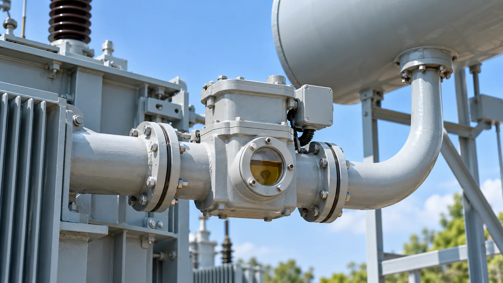
A Buchholz relay operation is evidence to investigate, not a diagnosis by itself. First identify the exact relay element and the alarm or trip contact that operated. Preserve event and gas evidence, correlate transformer indications, and let qualified transformer and protection personnel determine the cause. Following a protective trip, maintain the isolation/lockout required by the operating procedure; do not simply reset and re-energize.
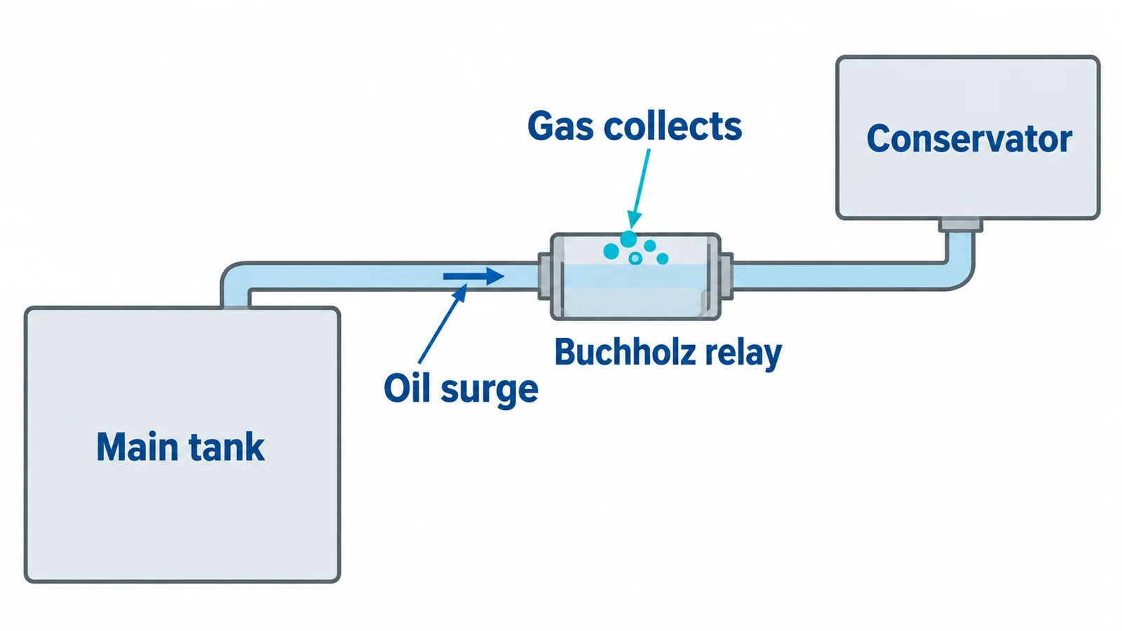
This guide concerns a main-tank gas/oil-flow relay fitted in the pipe between a conservator-type liquid-filled transformer’s main tank and conservator. It is not a troubleshooting procedure for dry-type or sealed-tank transformers, nor for every tap-changer protective relay. IEC 60076-22-1:2019 addresses protective devices for liquid-immersed transformers and reactors, but the installed relay’s design and the approved scheme determine the actual indications and trip logic.
Know what the relay can detect
In a common two-element arrangement, gas collecting in the relay displaces oil and operates an alarm element. A separate element responds to rapid oil flow toward the conservator and operates the trip circuit. Depending on the design, loss of oil level can also operate contacts. Thus “alarm” and “trip” do not map one-to-one to particular winding faults.
The US Bureau of Reclamation’s FIST 3-30 transformer maintenance manual, section 4.1.7, describes these mechanisms. It is historical utility guidance, not a universal current maintenance schedule. Use the exact relay manual and approved drawings for contact identification, operating thresholds and test methods.
The relay is not a universal detector for every transformer defect. A fault outside the relevant oil/gas path, or a developing problem without a detectable relay input, may require other protection or diagnostic methods. Conversely, a normal load or temperature display does not disprove a serious localized condition.
Preserve evidence before changing the state
The first investigation task is documentary and operational. From approved remote displays and records, capture the first-out indication, timestamps, alarm/trip sequence, breaker states, load, temperatures, oil-level indications, pressure-related alarms and recent maintenance. Distinguish the time a contact operated from the time an operator acknowledged an annunciator.
Avoid erasing alarms, draining collected gas, moving valves or cycling equipment merely to see whether the indication returns. Such actions can destroy evidence or alter the protection system. Close visual inspection, gas collection and hands-on checks belong to an approved qualified-person work plan, with isolation and pressure/oil hazards controlled. Never climb or approach energized transformer equipment to obtain a better view.
If smoke, oil release, fire indications or other emergency conditions are present, follow the site’s emergency response and exclusion arrangements. If an alarm occurs without a trip, notify the responsible operator/engineer immediately and apply the approved operating decision process; there is no universal safe waiting period in this article.
Separate physical operation from the signal circuit
Two questions need answers: what happened in the relay, and what did the protection/control system report or command? Keep both investigation tracks open until the evidence agrees.
| Observed event | Possible explanation—not a diagnosis | Evidence needed | Safe next action |
|---|---|---|---|
| Gas/alarm indication, without a recorded trip | Fault-related gas, trapped air after work, oil-level change or an indication-circuit problem | Exact element, collected-gas evidence, oil/level history, maintenance and event records | Escalate promptly; preserve evidence and follow the authorized operating decision. |
| Trip indication associated with the flow/low-level element | Rapid oil movement, significant oil-level loss, mechanical operation or a signal/test-circuit issue | First-out sequence, relay-specific indication, oil/pressure records and protection events | Maintain the trip isolation hold; qualified investigation before restoration. |
| Repeated gas indication after recent oil work | Residual air is plausible, but developing fault gas or air ingress remains possible | Work records, trend, gas composition, oil results and leak/level assessment | Do not dismiss as commissioning air without corroboration. |
| Control-system indication conflicts with local relay evidence | Incorrect point mapping, wiring/contact problem, test influence or missed/transient physical evidence | Approved schematic, contact mapping and controlled functional-test results | Investigate both tracks under the approved outage/test plan; do not bypass protection. |
| Gas indication accompanied by other transformer protection or pressure events | A common internal event is possible; timing alone does not identify its location | Correlated relay records, transformer evidence and specialist assessment | Preserve the lockout and coordinate transformer/protection review. |
Recent maintenance is a clue, not an automatic explanation. Reclamation’s FIST 3-31 diagnostics manual notes that trapped air can appear in a newly commissioned transformer, while gas in service-aged equipment requires investigation. Treat that as a hypothesis to verify, not permission to keep operating or discard samples.
Use gas and oil analysis without overstating the result
Collected relay gas and gases dissolved in tank oil are related but different samples. Their composition, sampling time and history matter. A qualified sampling plan should identify which samples are needed and preserve traceability before unnecessary venting or oil processing changes the evidence.
IEC 60567:2023 covers sampling free gases from gas-collecting relays and analysis of free and dissolved gases; it directs oil-sampling procedures to IEC 60475. It does not make an improvised collection method equivalent to a controlled laboratory sample.
IEC 60599:2022 provides interpretation guidance for dissolved and free gases in equipment using mineral insulating oil with cellulosic insulation. Other liquid/solid systems require caution. Its indications require engineering judgment, rather than serving as an automatic “gas ratio equals fault equals action” rule.
Do not identify a fault from gas color, smell or sound, and never use an improvised flame test. Likewise, one apparently normal tank-oil result is not a universal clearance of a relay trip. Sampling quality, operating history, trends and other findings must support the decision.
The transformer-noise diagnosis guide places acoustic clues in the same evidence-led context. Where differential protection also operated, examine its records using the relevant protection expertise; the differential-relay guide explains why settings and fault evidence cannot be replaced by a single symptom.
Outage checks must verify the complete scheme
Under an approved work plan, qualified personnel can examine relay installation, orientation, permitted pipe/valve arrangement, oil levels, leaks, mechanical condition and contact behavior against the exact instructions. Do not change a valve or flow setting based on a generic diagram. Check recent test activity and as-built signal mapping as part of the same investigation.
Functional verification must cover the appropriate relay elements and the intended alarm/trip path. A local test indication does not prove that the correct breaker or lockout operated. Equally, an annunciator test alone does not prove the hydraulic mechanism. The substation breaker-trip troubleshooting guide addresses the downstream command path. Any test isolation, temporary arrangement and restoration of protection must be controlled and documented; no bypass instructions are provided here.
Define release conditions, not just a reset action
Return to service requires a documented cause assessment, any corrective work, acceptable investigation/test results, verified protection restoration and authorization under the site’s procedure. If the cause remains unknown, neither a reset contact nor a normal display establishes fitness for service.
Keep the gas/oil reports, event chronology, drawings, corrective records and release decision with the transformer history. For specification context, the IEC 60076 transformer guide separates transformer requirements from accessory and protection evidence. The practical outcome is an explainable operating decision—not simply a relay that no longer shows an alarm.
Sources
- IEC 60076-22-1:2019 — protective devices for liquid-immersed transformers
- USBR FIST 3-30 — Transformer Maintenance, section 4.1.7
- USBR FIST 3-31 — Transformer Diagnostics, section 9.11
- IEC 60567:2023 — free- and dissolved-gas sampling and analysis
- IEC 60599:2022 — dissolved- and free-gas interpretation guidance