Short answer: A larger AWG number means a smaller conductor. Use this AWG wire size chart in three passes: find the nominal diameter and area, look up the copper or aluminum reference ampacity under the stated table conditions, then verify voltage drop and every installation correction before choosing a wire. The table is a lookup tool, not a complete installation instruction.
American Wire Gauge is a logarithmic size system. Each three-step change in AWG changes the nominal cross-sectional area by roughly a factor of two, which is why a chart is more reliable than a visual guess. The AWG number does not identify insulation, strand count, temperature rating, voltage rating or ampacity by itself.
AWG wire size chart
Ampacity changes with insulation temperature rating and installation conditions. These values are reference values; the adopted NEC edition and manufacturer data govern engineering use.
The copper and aluminum columns below reproduce the 75 C values shown in the public NFPA Table 310.16 committee document. They apply to the table conditions: conductors rated 0 V through 2,000 V, a 30 C ambient and not more than three current-carrying conductors in a raceway, cable or directly buried earth. They are not the final ampacity of every circuit.
The diameter and area columns are calculated from the nominal AWG definition. The resistance column uses the uncoated-copper direct-current values reproduced in NEC Chapter 9 Table 8 for the listed solid or Class B stranded construction. Blank ampacity and resistance cells mean that the cited tables do not provide that value for that size in the scope used here; they are not invitations to interpolate.
| AWG | Nominal diameter (mm) | Nominal diameter (in) | Nominal area (mm²) | Area (kcmil) | Cu DC resistance at 75 C (Ω/km) | 75 C Cu ampacity (A) | 75 C Al/CCA ampacity (A) |
|---|---|---|---|---|---|---|---|
| 4/0 | 11.684 | 0.4600 | 107.219 | 211.6 | 0.1996 | 230 | 180 |
| 3/0 | 10.405 | 0.4096 | 85.029 | 167.8 | 0.2512 | 200 | 155 |
| 2/0 | 9.266 | 0.3648 | 67.431 | 133.1 | 0.3170 | 175 | 135 |
| 1/0 | 8.251 | 0.3249 | 53.475 | 105.6 | 0.399 | 150 | 120 |
| 1 | 7.348 | 0.2893 | 42.408 | 0.505 | 130 | 100 | |
| 2 | 6.544 | 0.2576 | 33.631 | 0.634 | 115 | 90 | |
| 3 | 5.827 | 0.2294 | 26.670 | 0.802 | 100 | 75 | |
| 4 | 5.189 | 0.2043 | 21.151 | 1.010 | 85 | 65 | |
| 5 | 4.621 | 0.1819 | 16.773 | ||||
| 6 | 4.115 | 0.1620 | 13.302 | 1.608 | 65 | 50 | |
| 7 | 3.665 | 0.1443 | 10.549 | ||||
| 8 | 3.264 | 0.1285 | 8.366 | 2.506 | 50 | 40 | |
| 9 | 2.906 | 0.1144 | 6.634 | ||||
| 10 | 2.588 | 0.1019 | 5.261 | 3.984 | 35 | 30* | |
| 11 | 2.305 | 0.0907 | 4.172 | ||||
| 12 | 2.053 | 0.0808 | 3.309 | 6.34 | 25 | 20* | |
| 13 | 1.828 | 0.0720 | 2.624 | ||||
| 14 | 1.628 | 0.0641 | 2.081 | 10.1 | 20 | 15* | |
| 15 | 1.450 | 0.0571 | 1.650 | ||||
| 16 | 1.291 | 0.0508 | 1.309 | 16.0 | |||
| 17 | 1.150 | 0.0453 | 1.038 | ||||
| 18 | 1.024 | 0.0403 | 0.823 | 25.5 | |||
| 19 | 0.912 | 0.0359 | 0.653 | ||||
| 20 | 0.812 | 0.0320 | 0.518 | ||||
| 21 | 0.723 | 0.0285 | 0.410 | ||||
| 22 | 0.644 | 0.0253 | 0.326 | ||||
| 23 | 0.573 | 0.0226 | 0.258 | ||||
| 24 | 0.511 | 0.0201 | 0.205 | ||||
| 25 | 0.455 | 0.0179 | 0.162 | ||||
| 26 | 0.405 | 0.0159 | 0.129 | ||||
| 27 | 0.361 | 0.0142 | 0.102 | ||||
| 28 | 0.321 | 0.0126 | 0.081 | ||||
| 29 | 0.286 | 0.0113 | 0.064 | ||||
| 30 | 0.255 | 0.0100 | 0.051 | ||||
| 31 | 0.227 | 0.0089 | 0.040 | ||||
| 32 | 0.202 | 0.0080 | 0.032 | ||||
| 33 | 0.180 | 0.0071 | 0.025 | ||||
| 34 | 0.160 | 0.0063 | 0.020 | ||||
| 35 | 0.143 | 0.0056 | 0.016 | ||||
| 36 | 0.127 | 0.0050 | 0.013 | ||||
| 37 | 0.113 | 0.0045 | 0.010 | ||||
| 38 | 0.101 | 0.0040 | 0.008 | ||||
| 39 | 0.090 | 0.0035 | 0.006 | ||||
| 40 | 0.080 | 0.0031 | 0.005 |
Table notes
- Nominal diameter is calculated with
d = 0.127 x 92^((36 - AWG) / 39). For 4/0, 3/0, 2/0 and 1/0, use the numerical equivalents -3, -2, -1 and 0. Nominal area isA = pi x d^2 / 4. kcmilmeans thousands of circular mils. It is an area unit, not a current rating.- The 14, 12 and 10 AWG values marked
*in the aluminum/copper-clad aluminum column are limited by the table note to copper-clad aluminum. Do not treat them as ordinary aluminum conductor values. - Odd AWG sizes and 19-40 AWG are not given ampacity values in the cited Table 310.16 reproduction. Table 8 also does not list every small or odd size. Those cells remain blank rather than being estimated.
How to convert AWG to mm²
The AWG system starts from a defined geometric progression, not from a simple metric conversion table. The nominal diameter in millimetres is:
d = 0.127 x 92^((36 - AWG) / 39)
For 12 AWG:
d = 0.127 x 92^((36 - 12) / 39) = 2.053 mm
The circular cross-sectional area is:
A = pi x d^2 / 4
A = pi x (2.053 mm)^2 / 4 = 3.31 mm²
That is why 12 AWG is commonly written as approximately 3.31 mm². The conversion describes nominal conductor area. It does not mean that a metric terminal marked 4 mm² is automatically equivalent to 12 AWG, and it does not account for stranding, compacting or the outside diameter over insulation.
Quick mm² reference
| AWG | Nominal area |
|---|---|
| 12 AWG | approximately 3.31 mm² |
| 10 AWG | approximately 5.26 mm² |
| 8 AWG | approximately 8.37 mm² |
| 6 AWG | approximately 13.3 mm² |
| 4 AWG | approximately 21.2 mm² |
| 2 AWG | approximately 33.6 mm² |
These are nominal values calculated from the AWG definition. The exact construction can have a different overall diameter because of strand count, compacting, insulation and jacket thickness.
Three useful AWG rules
The logarithmic scale produces three approximations that are useful for orientation:
- Three AWG steps smaller: the nominal area is approximately double. For example, the geometric progression makes the area at 9 AWG about twice the area at 12 AWG.
- Six AWG steps smaller: the nominal diameter is approximately double.
- Ten AWG steps smaller: the nominal area is approximately ten times larger.
These are geometric rules, not ampacity rules. A conductor with twice the metal area does not automatically have twice the usable ampacity after all installation factors are applied.
Copper versus aluminum at the same AWG
At the same AWG, aluminum generally has lower ampacity than copper. The Table 310.16 reference columns show the pattern clearly: 6 AWG copper is listed at 65 A in the 75 C column, while 6 AWG aluminum is listed at 50 A. Moving about two AWG steps larger in aluminum often produces a table value closer to the copper value, but the exact comparison must use the adopted table and the actual conductor type.
For example, 6 AWG copper and 4 AWG aluminum are both listed at 65 A in the 75 C reference columns. That does not make the two conductors interchangeable. The terminations must accept aluminum, the connector must be suitable for the conductor material and size, and the installation method must be correct for both.
Do not read the aluminum column as a simple material swap. The 14, 12 and 10 AWG entries marked with an asterisk are copper-clad aluminum values under the source table note. Copper-clad aluminum is not the same product as ordinary aluminum building wire. Also check the equipment terminal marking: a terminal rated only for copper cannot accept aluminum merely because a larger aluminum size is chosen.
How to read the chart without overreading it
Start with the physical size. The diameter and mm² columns answer the question, “What conductor geometry does this AWG designation describe?” Use them when comparing a cable designation with a terminal’s published conductor range or when a drawing mixes AWG and metric units.
The resistance column answers a different question. It gives the listed conductor’s direct-current resistance per kilometre at the table’s stated temperature and construction. That value is useful for a DC voltage-drop estimate or for checking whether a proposed run is in the right order of magnitude. It is not a complete AC impedance model. Alternating-current circuits can have reactance, skin effect and proximity effects that a single DC resistance column does not capture. Use the conductor and installation data appropriate to the actual study when those effects matter.
Next, read the ampacity column only after confirming the table conditions. The reference value must still be checked for ambient temperature, conductor count, insulation rating, termination temperature, wiring method and any special rule in the adopted code. A 75 C insulation marking does not prove that every terminal in the circuit is rated for 75 C use.
Then check voltage drop. Ampacity answers whether the conductor can carry current without exceeding its thermal basis; it does not answer whether the load will receive an acceptable voltage. The separate voltage-drop calculation guide shows the conductor-length calculation, and the feeder cable-sizing workflow places that calculation alongside protection and installation checks.
Finally, record the adopted code edition and the exact table or manufacturer data used. A chart copied without its edition and conditions is not an engineering record. The companion Wire Size Guide, delivered in the same batch and intended to publish after this reference page, covers the current, distance and correction method in detail. This page deliberately does not repeat that workflow.
The same separation applies to busbars. A copper busbar ampacity and derating guide uses a different geometry, mounting and thermal basis, so a busbar current density should not be pasted into an AWG table.
Four common mistakes
Treating ampacity as a fixed property of AWG
Ampacity is not a property of the copper or aluminum alone. Insulation temperature rating, ambient temperature, conductor grouping, installation method, terminal rating and the adopted code all affect the usable value.
Ignoring the termination temperature
The conductor insulation may have a higher temperature rating than the breaker, load equipment or terminal block. The lower controlling termination rating can limit the usable ampacity. Check the exact equipment marking rather than assuming that a 90 C conductor can be terminated at its 90 C table value.
Using the copper column for aluminum
The aluminum column is lower for a reason. The conductor has different resistivity and thermal behavior, and the termination must be identified for aluminum. A larger aluminum size is not a universal substitute for copper without checking the connector, terminal, preparation and torque requirements.
Interpolating blank cells
An odd AWG size is not made valid by drawing a line between two neighboring table values. Use an approved engineering method, the exact adopted code text or manufacturer data. For a reference chart, a blank cell is safer and more truthful than an invented number.
FAQ
Does a higher AWG number mean thicker wire?
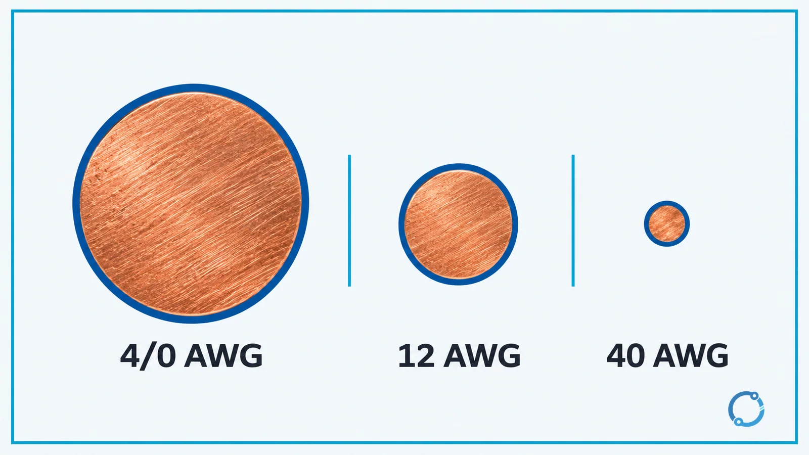
No. A higher AWG number means a smaller nominal conductor. For example, 12 AWG is smaller than 8 AWG, and 40 AWG is much smaller than 12 AWG.
What is 12 AWG in mm²?
The nominal area of 12 AWG is approximately 3.31 mm² when calculated from the AWG definition. Actual cable construction and insulation dimensions can differ.
Are AWG ampacity values universal?
No. The values in this chart are reference values from the 75 C column of the cited Table 310.16 reproduction under its stated conditions. Ambient temperature, conductor grouping, insulation, terminals and the adopted code can change the usable ampacity.
Why are some cells blank?
The cited NEC tables do not provide a value for every odd or small AWG size within the scope used here. Those cells are left blank instead of being estimated by interpolation.
Is aluminum ampacity the same as copper at the same AWG?
No. Aluminum generally has a lower same-size ampacity, and the terminations must be suitable for aluminum. A larger aluminum size may produce a comparable table value, but the exact selection still requires the adopted table and installation checks.