Short answer: For a balanced three-phase load with approximately sinusoidal voltage and current:
P = sqrt(3) x VL x IL x PF
S = sqrt(3) x VL x IL
Q = sqrt(3) x VL x IL x sin(phi)
Here, P is real power in watts, S is apparent power in volt-amperes, Q is reactive power in reactive volt-amperes, VL is line-to-line RMS voltage, IL is RMS line current, and PF is power factor. The multiplier sqrt(3) is approximately 1.732.
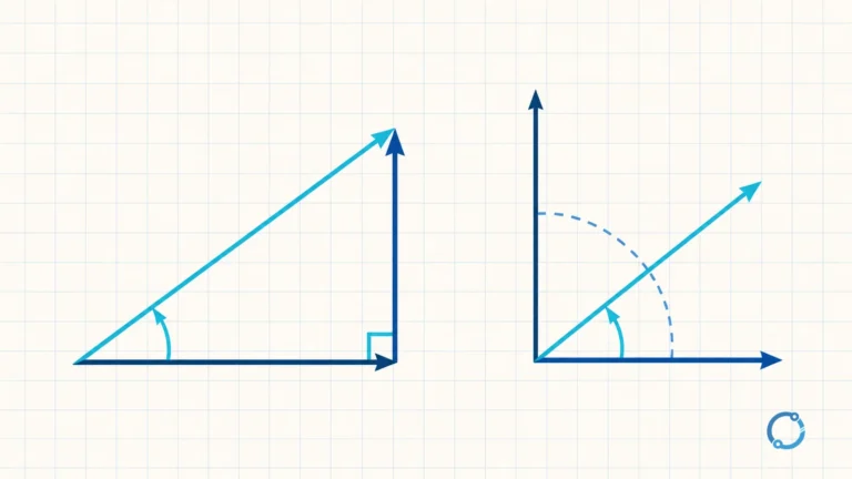
Those three equations answer related questions. The apparent-power equation tells you how much total electrical capacity the load requires. The real-power equation tells you how much of that apparent power performs useful work. The reactive-power equation describes the component associated with the phase displacement between voltage and current. They apply directly only when the load is balanced and the waveforms are close enough to sinusoidal for a single displacement angle to be meaningful.
This page is the calculation layer. It shows how to move between kW, kVA and line current without re-deriving transformer winding relationships. The meaning of power factor explains why the cosine term appears, while the wye and delta pages linked below handle line-versus-phase quantities inside transformer connections.
The balanced three-phase formulas
For a balanced load:
| Quantity | Formula | Unit | Main use |
|---|---|---|---|
| Apparent power | S = sqrt(3) x VL x IL |
VA or kVA | Source, transformer or feeder capacity |
| Real power | P = sqrt(3) x VL x IL x PF |
W or kW | Useful power delivered to the load |
| Reactive power | Q = sqrt(3) x VL x IL x sin(phi) |
var or kvar | Reactive component associated with phase displacement |
| Single-phase real power | P = V x I x PF |
W or kW | Comparison only; uses single-phase voltage and current |
The line voltage VL is the voltage between two line conductors. The line current IL is the current in one line conductor. Both must be RMS values when the formulas are written this way.
The formula does not tell you that a particular cable, breaker, transformer or meter is suitable. It gives an electrical load result. Equipment selection still requires the applicable installation rules, correction factors, duty cycle and manufacturer data.
Why the square root of three appears
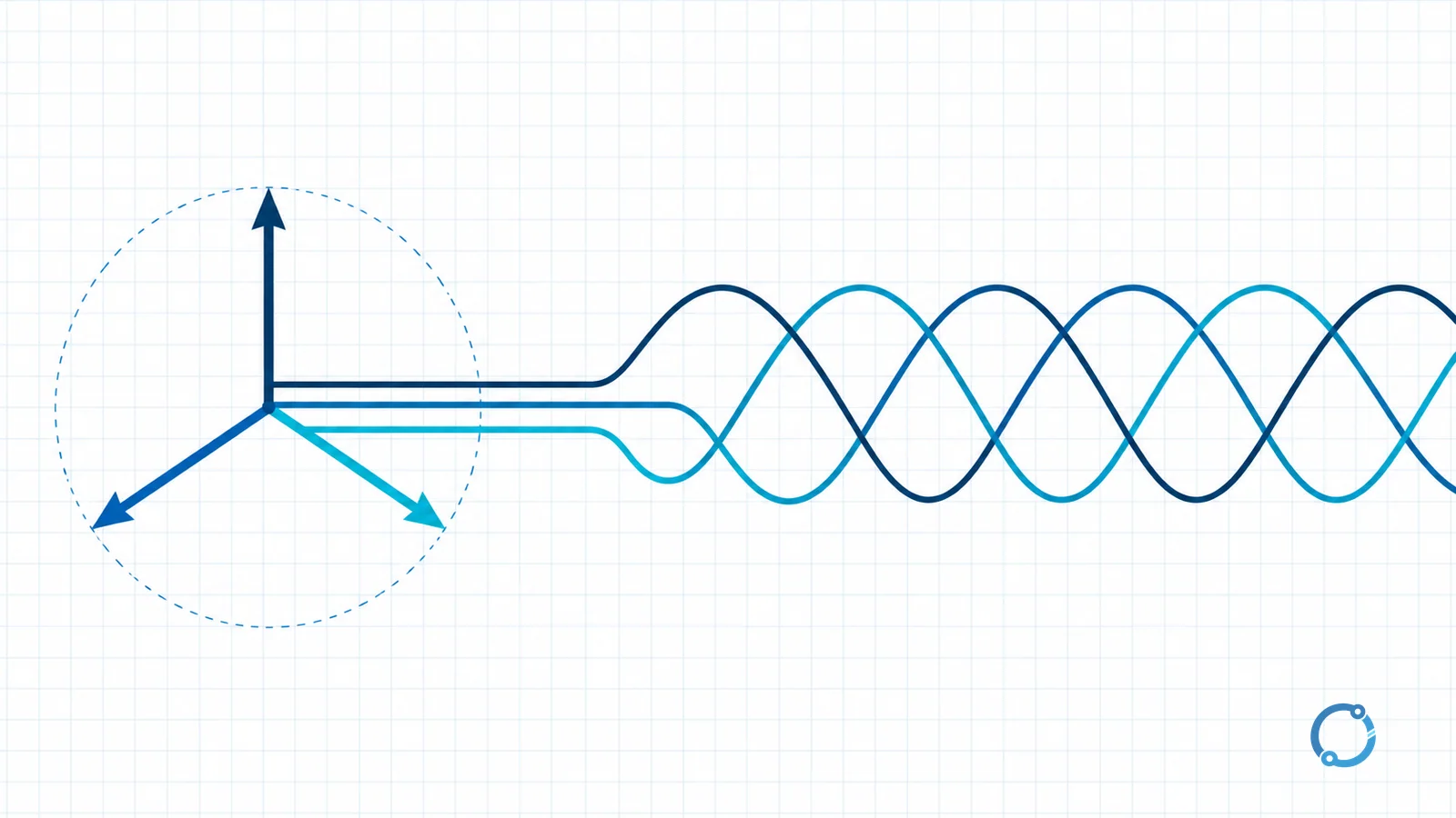
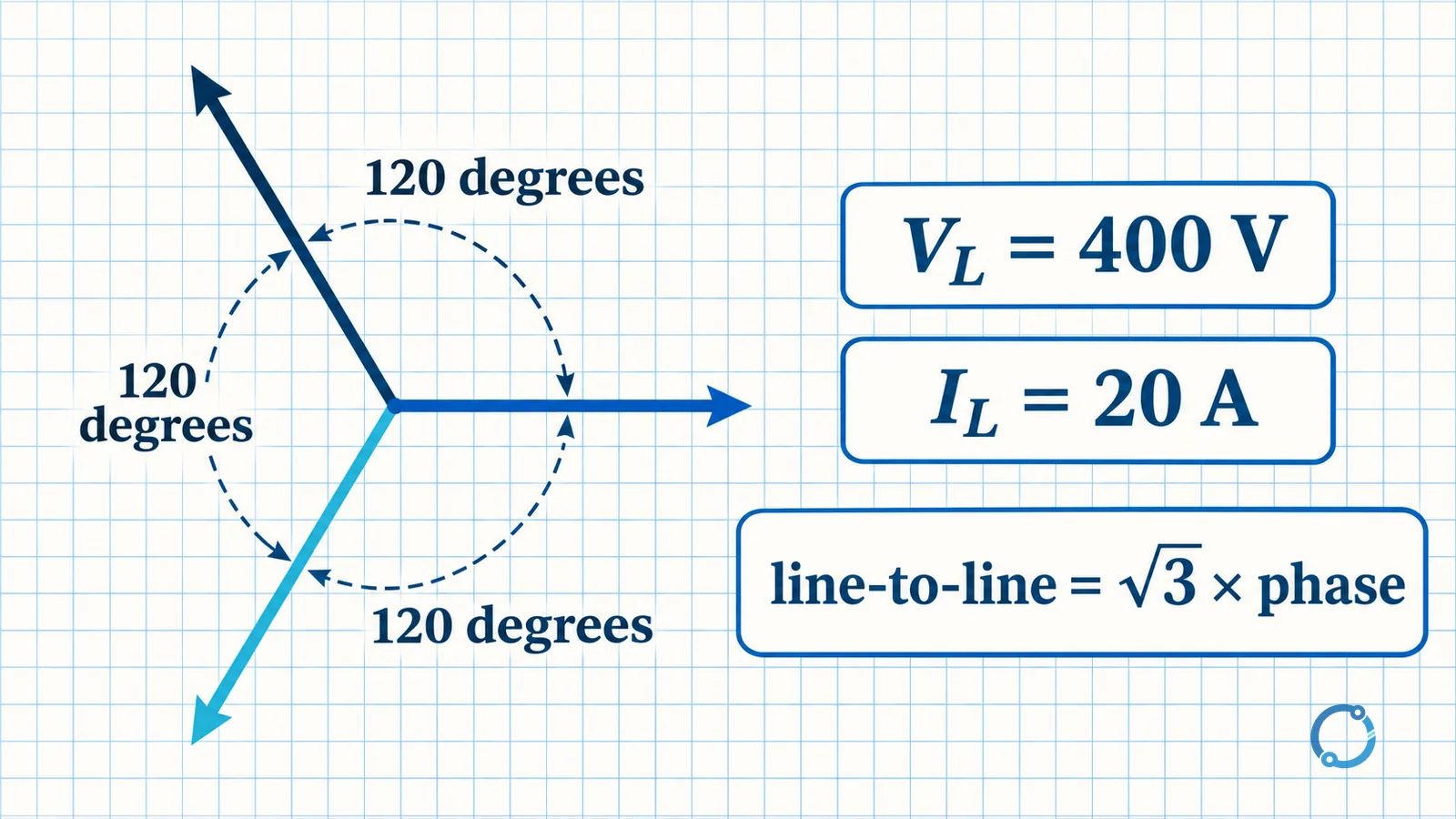
Three phase voltages in a balanced system are displaced from one another by 120 degrees. Their vector sum is zero when the system is balanced. The line-to-line voltage is the vector difference between two phase voltages, not merely the arithmetic difference between their magnitudes.
In a wye-connected source, the magnitude relationship between line voltage and phase voltage is:
VL = sqrt(3) x V_phase
The line current equals the phase current in that wye branch. Substituting the line quantities into the sum of the three phase powers produces the familiar sqrt(3) multiplier. In a delta connection, the voltage and current relationships change, but the resulting balanced three-phase power equation still uses line voltage and line current.
That is why the calculation works for either connection once the inputs are defined as line quantities. It is not a second set of transformer equations. The detailed vector relationships are covered in wye transformer line and phase calculations and delta transformer line and phase calculations.
When the balanced formula applies
The formula assumes balanced phase impedances and a reasonably sinusoidal supply. Balanced means the phase voltage magnitudes are approximately equal, the phase currents are approximately equal, and the phase displacements are evenly distributed. In that condition, one set of line voltage, line current and power-factor values can represent the three-phase load.
An unbalanced load needs a phase-by-phase calculation. Measuring one line current and applying the balanced equation can hide a heavily loaded phase, neutral current or voltage displacement. The voltage-unbalance measurement and motor effect page explains why unbalanced voltage needs separate treatment.
When voltage and current contain significant harmonic distortion, the displacement angle between the fundamental components no longer describes the complete relationship between real and apparent power. The true power factor can differ from the fundamental displacement factor. The dirty electricity and waveform distortion explanation provides the terminology. Detailed harmonic calculation is outside this page.
The formulas also do not remove the difference between input electrical power and mechanical output power. A motor nameplate may state output power, while a three-phase input calculation uses electrical input power. If efficiency is known, the relationship is:
electrical input power = mechanical output power / efficiency
No efficiency value is assumed in the examples below. All given power values are treated as electrical input-side quantities.
Worked example 1: line voltage and current to kVA and kW
Consider a balanced three-phase load supplied at:
- Line voltage
VL = 400 V RMS - Line current
IL = 20 A RMS - Power factor
PF = 0.85
These are hypothetical teaching inputs. They are not a product rating or a recommended design point.
Calculate apparent power
S = sqrt(3) x VL x IL
S = 1.732 x 400 x 20
S = 13,856 VA
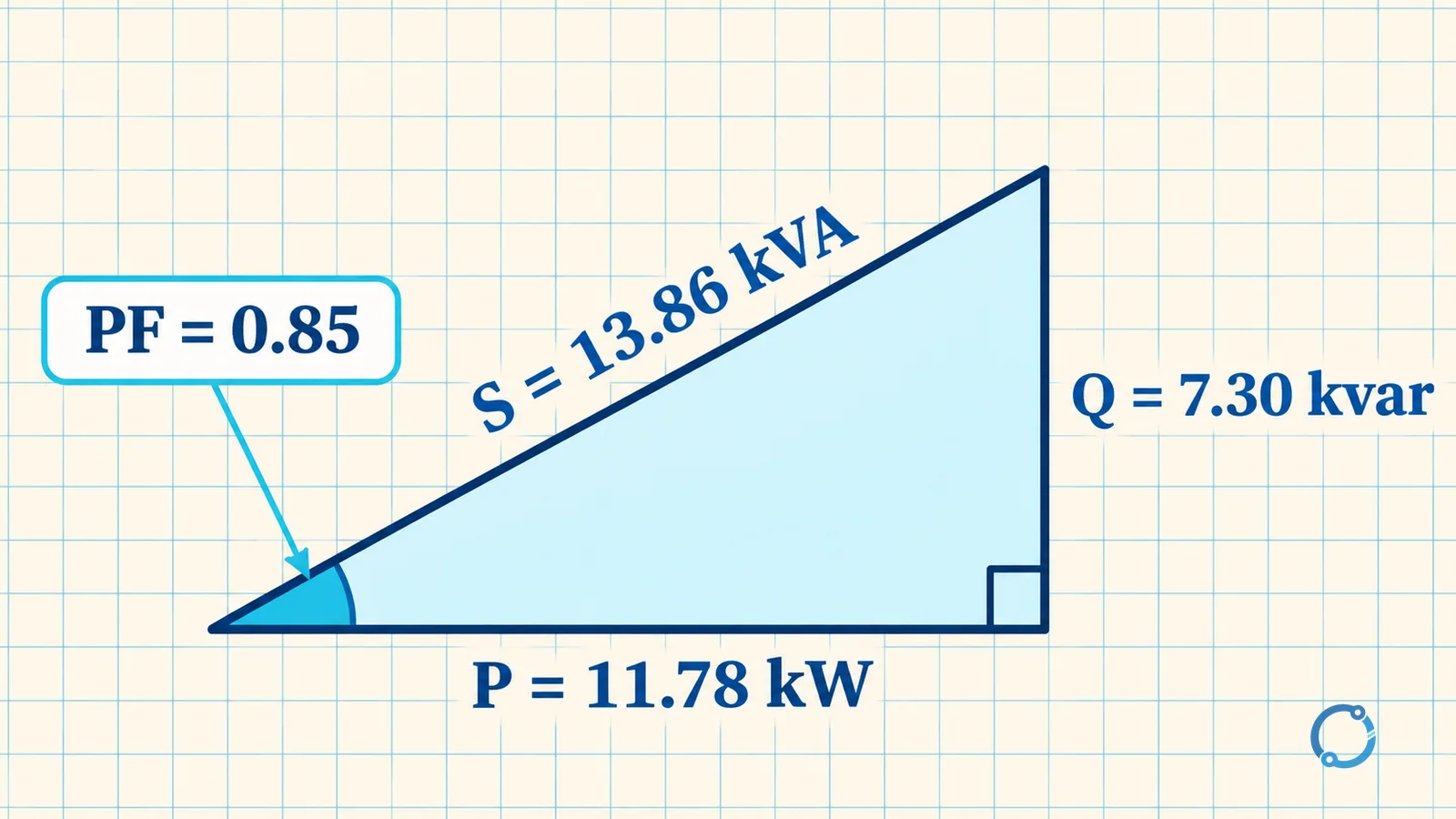
S = 13.86 kVA when rounded to two decimal places.
The apparent power is approximately 13.86 kVA. This is the magnitude associated with the voltage and current product before the power-factor component is separated.
Calculate real power
P = sqrt(3) x VL x IL x PF
P = 1.732 x 400 x 20 x 0.85
P = 11,777.6 W
P = 11.78 kW when rounded to two decimal places.
The result is consistent with taking 85 percent of the apparent power:
13.86 kVA x 0.85 = 11.78 kW
The exact intermediate W value is 11,777.6 W, while the rounded kVA route gives an approximate display result. Keep enough precision in intermediate work so rounding does not change the intended answer.
Calculate reactive power
The sinusoidal power triangle gives:
Q = sqrt(S^2 - P^2)
Q = sqrt(13.86^2 - 11.78^2)
Q = sqrt(192.0996 - 138.7684)
Q = sqrt(53.3312)
Q = 7.30 kvar when rounded to two decimal places.
The checked set is therefore 13.86 kVA, 11.78 kW and 7.30 kvar.
Worked example 2: kW to line current
Now reverse the task. A balanced three-phase load has:
- Electrical input power
P = 15 kW - Line voltage
VL = 400 V RMS - Power factor
PF = 0.85
Start from the real-power formula and rearrange it:
IL = P / (sqrt(3) x VL x PF)
Use power in watts:
IL = 15,000 / (1.732 x 400 x 0.85)
Calculate the denominator:
1.732 x 400 x 0.85 = 588.88, approximately 589.0
Divide:
IL = 15,000 / 589.0 = 25.47 A
IL = 25.5 A when rounded to one decimal place.
This is the line current associated with the stated balanced load and assumed power factor. It is not a cable ampacity or a breaker-setting recommendation.
Three-phase versus single-phase current
The difference in conductor current can be substantial when the same real power is delivered at a lower single-phase voltage.
Take the first example’s 11.78 kW and keep the same 0.85 power factor. For a single-phase supply at 230 V, the real-power relationship is:
P = V x I x PF
Rearrange:
I = P / (V x PF)
Use the intermediate W value:
I = 11,778 / (230 x 0.85)
I = 11,778 / 195.5
I = 60.2 A when rounded to one decimal place.
At 400 V three-phase, the same rounded real power was associated with a line current of 20 A in Example 1. At 230 V single-phase, it is about 60.2 A. The much larger single-phase conductor current is one practical reason industrial power distribution commonly uses three-phase circuits for substantial loads.
That comparison assumes the stated voltages, power factor and load behavior. It does not prove that every three-phase installation is more efficient, and it does not choose a service or conductor. Voltage drop remains a separate calculation, as does the distinction between kW and kWh when energy over time rather than power demand is the question.
Conversion formulas for balanced loads
Use line-to-line RMS voltage in every row. Keep PF dimensionless and convert watts to kilowatts by dividing by 1,000.
| Task | Formula | Application |
|---|---|---|
| kW to amperes | IL = P_kW x 1000 / (sqrt(3) x VL x PF) |
Same structure as the 15 kW example |
| Amperes to kW | P_kW = sqrt(3) x VL x IL x PF / 1000 |
Use the 400 V, 20 A, 0.85 PF example and check 11.78 kW |
| kVA to amperes | IL = S_kVA x 1000 / (sqrt(3) x VL) |
Use the 13.86 kVA example and check approximately 20 A |
| Amperes to kVA | S_kVA = sqrt(3) x VL x IL / 1000 |
Use 400 V and 20 A and check 13.86 kVA |
| Power factor from P and S | PF = P_kW / S_kVA |
Use 11.78 divided by 13.86 and check approximately 0.85 |
The same notation can appear in transformer data, but the calculation task is different. A transformer type may be described using rated apparent power, while a load calculation asks what the connected equipment draws under stated operating conditions. Keep rating, load and measured values as separate concepts.
Common mistakes
Substituting phase voltage for line voltage
The formulas in this article use line-to-line voltage. If phase voltage is substituted without changing the formula, the apparent-power result can be too small by a factor of approximately sqrt(3). In a wye system, first identify whether the meter is connected line-to-line or line-to-neutral.
Mixing watts and kilowatts
The numerator and denominator must use compatible units. A 15 kW load is 15,000 W when inserted into the ampere calculation. Dropping the conversion factor produces an answer that is 1,000 times too small.
Treating motor output power as electrical input power
A motor nameplate may describe mechanical output, not the electrical input at the terminals. Converting output to input requires efficiency and the correct operating point. The examples here are electrical input quantities, so no motor-efficiency value is needed or implied.
Applying a balanced formula to an unbalanced system
The equation depends on equal phase magnitudes and the same phase displacement in each phase. An unbalanced system needs phase-by-phase or properly defined symmetrical-component analysis. Do not average an obviously unequal set of line currents and call the result a balanced load.
A practical calculation sequence
- Confirm that the system is approximately balanced and sinusoidal.
- Identify whether voltage is line-to-line RMS.
- Record line current RMS and power factor at the same operating point.
- Choose kVA, kW or ampere conversion based on the known quantities.
- Carry units through the calculation and round only at the end.
- Check the result against the power triangle or a second formula.
- Treat the result as an input to protection, voltage-drop and equipment-selection work, not as the complete design.
This sequence helps catch the most common mistakes because each step forces an assumption into the open. It also prevents a reader from comparing a phase current with a line voltage or a kW value with a kVA value as though the quantities were interchangeable.
Further reading
Use the VIOX three-phase power calculator to check a balanced calculation after entering the same assumptions. A calculator can reproduce the arithmetic quickly, but it cannot decide whether the load is balanced, whether the voltage is line-to-line RMS or whether the equipment requires a different operating condition. Keep a manual result and the stated assumptions for review.
FAQ
What is the three-phase power formula?
For a balanced sinusoidal load, real power is P = sqrt(3) x line voltage x line current x power factor. Apparent power is S = sqrt(3) x line voltage x line current. Use RMS line quantities and verify that the load is balanced.
Why is the square root of three used?
Balanced phase voltages are separated by 120 degrees. The line-to-line voltage is the vector difference between two phase voltages, so its magnitude is related to the phase voltage by sqrt(3) in a wye source. The same balanced power relationship results when expressed in line quantities.
How do I calculate amps from kW in a three-phase circuit?
Rearrange the real-power formula: line current = kW x 1000 / (sqrt(3) x line voltage x power factor). For a balanced 15 kW, 400 V, 0.85 PF example, the result is approximately 25.5 A.
What is the difference between kW and kVA?
kW is real power that performs work or produces heat. kVA is apparent power, the product of RMS voltage and current magnitudes before the power-factor component is separated. For a sinusoidal load, kW equals kVA multiplied by power factor.
Can I use these formulas for an unbalanced load?
No, not as a single balanced-load result. An unbalanced system requires phase-by-phase analysis or an appropriate multi-phase method. The balanced equation remains useful only when its assumptions are reasonably satisfied.