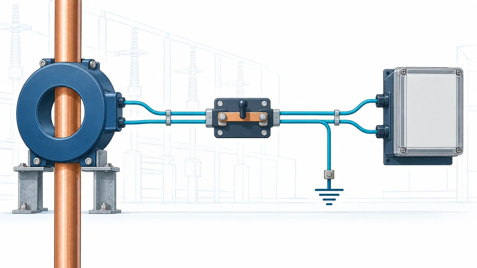
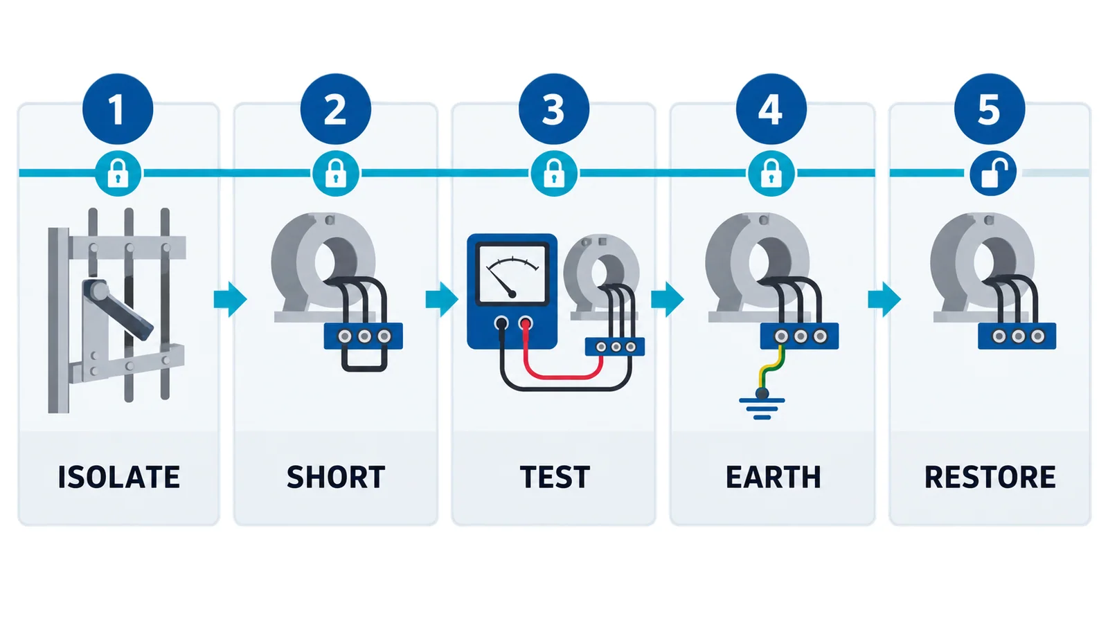
Before commissioning an inductive current transformer (CT), de-energize and secure the primary circuit, keep every unused or incomplete secondary shorted, install one designated secondary grounding point, verify nameplate/ratio/polarity and wiring continuity, test the complete burden circuit, then remove temporary shorts only under the approved energization procedure.
Never open a CT secondary while primary current can flow. California’s current-transformer secondary safety rule prohibits opening the secondary while the transformer is energized and requires bridging the circuit when the primary cannot be de-energized. Other jurisdictions have their own requirements; the safe engineering principle remains the same.
Scope and competence boundary
This workflow addresses newly installed inductive CTs for AC metering and protection circuits. IEC 61869-2:2012 applies to newly manufactured inductive CTs used with measuring instruments or protective devices at rated frequencies from 15 Hz to 100 Hz.
Testing must be planned and performed by qualified personnel using project procedures, approved test equipment and the CT/relay documentation. This article does not authorize energized work, live primary injection, alteration of sealed metering circuits or equipment repair.
Why an open secondary is hazardous
A CT primary is in series with the power circuit. Under normal operation, secondary current flows through a low-impedance burden and counteracts core flux. If the secondary opens while primary current continues, flux and secondary voltage can rise sharply, creating shock, insulation and equipment hazards.
The U.S. Bureau of Reclamation’s FIST 3-8 maintenance guidance warns that CT secondaries must not be open-circuited with the primary energized and recommends shorting devices or bars to maintain a closed circuit.
This is different from a voltage transformer, whose secondary must not be short-circuited. Label test switches and procedures so the two device types cannot be confused.
Stage 1: review the design
Collect:
- one-line and AC/DC schematics;
- CT manufacturer, type and serial number;
- ratio and tap selection;
- metering or protection accuracy class;
- rated burden/output;
- knee-point or transient data where specified;
- polarity markings;
- primary orientation;
- secondary terminal designations;
- earthing point;
- shorting/test-switch arrangement;
- relay/meter input burden;
- cable size, route and resistance;
- required commissioning tests and acceptance values.
IEC TR 61869-100:2017 gives application guidance for inductive protection CTs meeting IEC 61869-2 and addresses CT behavior under standardized short-circuit signals and design responsibilities.
Do not select a tap from memory. A multi-ratio CT connected to the wrong terminals can produce an incorrect ratio or leave an unused winding section in an unintended state.
Stage 2: establish a safe work state
Before touching primary or secondary wiring:
- identify every possible source and backfeed path;
- open, secure and tag the applicable disconnecting means;
- inhibit remote and automatic operation;
- verify absence of voltage using the approved procedure;
- apply protective grounds where required;
- confirm the CT secondary is shorted through an approved device;
- prove the correct circuit and terminal identifiers.
If the primary cannot be de-energized, do not improvise. Follow the jurisdictional energized-work rules and approved bridging method. A loose jumper placed after a circuit is opened is not a safe substitute for a make-before-break CT shorting switch.
Stage 3: inspect mechanical installation
Verify:
- CT type and ratio match the drawing;
- primary conductor passes through the intended window;
- P1/P2 or equivalent orientation matches source/load convention;
- mounting is secure without stressing the core or enclosure;
- required clearances are maintained;
- secondary terminal cover and sealing provisions are intact;
- unused cores/taps are handled per the design;
- secondary cable is supported and protected;
- identification is visible and consistent.
For split-core CTs, inspect mating surfaces and latch closure according to the product instructions. Debris or a gap can alter performance. Product-specific instructions belong in the project record even when they are not published as OHELE links.
Stage 4: wire polarity and phase correctly
CT polarity determines the direction of measured current and is essential for:
- differential protection;
- directional overcurrent;
- power and energy measurement;
- residual/ground-fault summation;
- transformer/vector compensation;
- negative-sequence functions.
Trace primary polarity to secondary polarity and relay terminal. Keep a phase-by-phase continuity record rather than relying on wire color.
For three phases, verify:
- phase assignment;
- source/load orientation;
- star point or residual connection;
- cable cores and terminal numbers;
- test-switch routing;
- relay current-input polarity;
- neutral/earth CT relationship where used.
A ratio test can pass while polarity is reversed. Test these as separate properties.
Stage 5: install one intentional secondary grounding point
A CT secondary circuit is commonly grounded at one designated point to control its reference potential. The project design should define the point, usually in the switchgear, marshalling cabinet or relay panel.
Verify:
- exactly one intended ground per galvanically connected secondary circuit unless the engineered design says otherwise;
- a durable, traceable connection;
- no accidental second ground through shields, test equipment or multiple panels;
- grounding of cable screens according to the protection/EMC design;
- separation of protective grounding from signal-screen decisions.
Multiple grounds can create circulating current and measurement error; no intentional ground can leave the circuit floating. Do not move the grounding point without a protection-engineering review.
Stage 6: calculate the burden
CT burden includes relay/meter inputs, leads, test switches and connections.
For a two-wire copper secondary lead:
Rlead = 2ρL / A
Approximate lead burden at rated secondary current:
VAlead = Is²Rlead
Total burden:
VAtotal = VAdevices + VAleads + VAconnections
For example, assume:
- 5 A secondary;
- 30 m one-way copper lead;
- 2.5 mm² conductor;
- illustrative copper resistivity 0.0175 Ω·mm²/m.
Rlead = 2 × 0.0175 × 30 / 2.5 = 0.42 Ω
VAlead = 5² × 0.42 = 10.5 VA
That excludes relay, switch and connection burden. A 1 A secondary under the same resistance would have 0.42 VA lead burden, showing why secondary rating and lead length matter.
Use actual conductor temperature/resistance and device data for the project. Compare total burden with the CT’s applicable accuracy and protection requirements.
Stage 7: perform de-energized electrical checks
The exact test set depends on CT type and project specification. A typical sequence includes:
Continuity and grounding
- prove each secondary loop;
- verify no unintended open circuit;
- confirm the designated earth point;
- check for unintended additional earths with connections isolated as the procedure requires.
Insulation resistance
Test between appropriate circuits and earth only at approved test voltage after isolating sensitive electronics. Do not apply an insulation tester through relay inputs, transducers or electronic devices unless the test plan explicitly permits it.
Ratio
Use approved low-current primary injection or CT analyzer methods. Compare measured ratio with the selected tap and acceptance tolerance. Confirm the test current and instrument range are adequate.
Polarity
Use an approved polarity test and document primary/secondary terminal correspondence. Avoid uncontrolled “battery kick” methods where modern electronics are connected or the project procedure does not authorize them.
Excitation and winding resistance
Perform when required for protection CTs, differential schemes, matched cores or condition baseline. Demagnetize the core after excitation testing when the test method requires it.
Secondary injection
Secondary injection tests the relay/meter circuit and logic but does not prove the primary conductor, CT ratio or polarity by itself.
Primary injection
Primary injection can prove the complete chain from primary current through CT, wiring, relay/meter and trip logic. It requires a controlled high-current test, equipment isolation and a specific safety plan. It is not a casual field check.
Stage 8: verify protection and metering functions
For protection:
- confirm current magnitude and angle;
- verify phase and residual quantities;
- test directional/differential logic as applicable;
- verify trip path and breaker indication;
- confirm settings and CT ratio in the relay;
- check saturation/transient assumptions against the protection study.
For metering:
- confirm phase association;
- check current and power direction;
- compare against a reference under controlled load where permitted;
- verify meter ratio and multiplier;
- secure seals and records where revenue metering applies.
Do not use load current as the first polarity test if an incorrect connection could trip equipment or create billing error.
Stage 9: controlled transition to service
Use a documented state table:
| State | Primary | Secondary | Allowed action |
|---|---|---|---|
| installation | de-energized/grounded | shorted | wiring and approved tests |
| circuit complete | de-energized | burden connected and short retained | final continuity/polarity checks |
| pre-energization | isolated | verified burden, designated ground, short state per procedure | independent review |
| service | energized | closed through burden | monitoring only |
| relay removal with primary energized | energized | bridged by approved make-before-break device | qualified procedure only |
Before energization, two-person verification is prudent for critical protection circuits. Confirm all temporary test leads are removed, permanent grounds are correct, shorting links are in the required service state and covers are installed.
Common errors
| Error | Consequence | Prevention |
|---|---|---|
| secondary opened under load | hazardous voltage and possible damage | approved shorting/bridging sequence |
| wrong ratio tap | scaling and protection error | terminal-by-terminal ratio record |
| reversed polarity | directional/differential/metering error | separate polarity test |
| two secondary grounds | circulating current or error | isolation check of complete circuit |
| no ground | uncontrolled secondary reference | designated grounding point |
| excessive burden | accuracy loss or protection saturation | burden calculation and measurement |
| insulation test through electronics | equipment damage | isolate sensitive devices |
| secondary injection treated as full proof | primary path remains unverified | use appropriate end-to-end test |
Commissioning record
Record:
- asset and CT identification;
- drawing revision;
- ratio/tap;
- polarity and phase;
- winding/loop resistance;
- insulation test voltage and results;
- burden calculation or measurement;
- ratio and excitation results where required;
- grounding point;
- shorting-link service position;
- relay/meter scaling;
- test equipment and calibration status;
- test personnel, date and approvals;
- deviations and corrective actions.
Bottom line
Safe CT commissioning is a controlled transition from an isolated primary and shorted secondary to a verified closed burden circuit. Prove identity, ratio, polarity, burden, insulation and one intentional grounding point before service. Keep the secondary closed whenever primary current can flow, and treat every removal or test as a state-controlled protection task.
If an installation check reveals a rating or application mismatch, return to the CT ratio, burden and accuracy selection criteria. For metering-system verification, continue with CT/VT scaling and commissioning checks.