
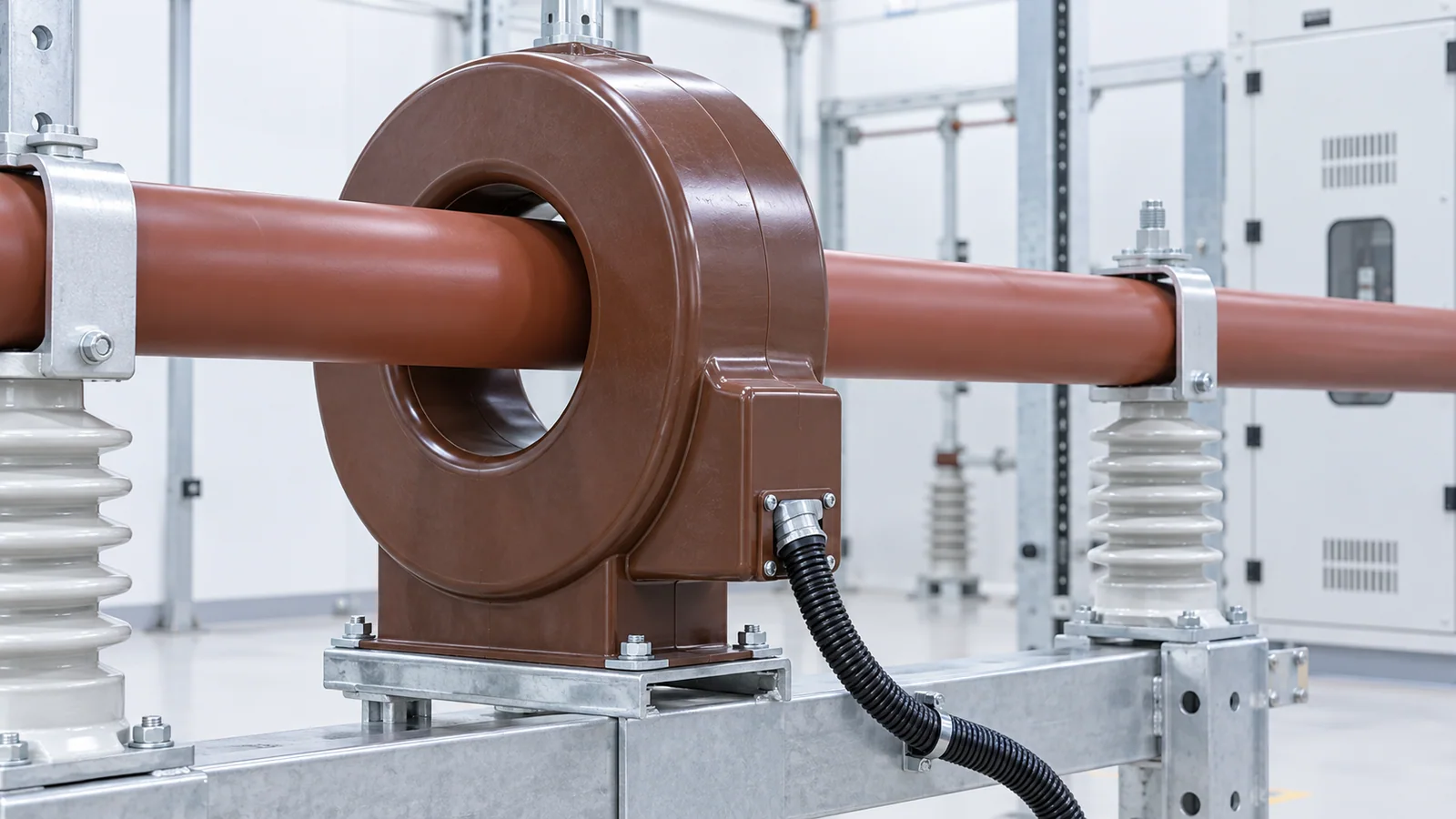
For an alternating-current power-system current transformer (CT), select the ratio, each core’s duty and accuracy, the complete secondary burden, and short-circuit withstand as one specification. A ratio that displays normal load well can still saturate during a fault; a protection core chosen for fault performance can be a poor revenue-metering choice. Start with the actual load and fault envelope, not a preferred catalog ratio.
This is a selection workflow, not a live-wiring procedure. It uses the IEC instrument-transformer framework; IEEE classes and notation are not interchangeable with IEC classes. IEC 61869-2 covers inductive CT requirements, while IEEE C57.13-2016 provides a separate U.S. instrument-transformer framework. The relay manufacturer’s CT requirements and the project protection study remain decisive.
Define the circuits before picking a ratio
Record maximum continuous primary current, minimum current to be measured, motor or transformer inrush, the maximum and minimum fault currents at the CT, system frequency, insulation level, environmental duty and physical mounting. Then list every secondary circuit: revenue meter, power-quality meter, overcurrent relay, differential relay, disturbance recorder and any shared devices. Decide whether they require separate cores.
Metering and protection have different failure concerns. A meter needs useful accuracy over its specified operating range. A protection relay needs a faithful enough secondary signal over the relevant fault range and, for some schemes, during the transient interval. Do not assume one generic accuracy marking satisfies both.
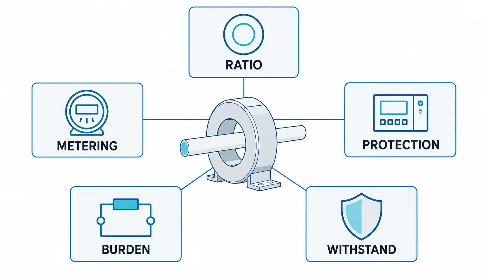
Gate 1: ratio and secondary current
Choose a standard primary rating that covers the expected continuous and emergency current within the CT’s stated thermal limits, while keeping low-load measurement usable. For example, a 600/5 A CT nominally produces 5 A at 600 A primary and 1 A at 120 A primary, before ratio and phase errors. It is not evidence that the CT is accurate at every load or fault current.
Specify whether the secondary circuit is 1 A or 5 A according to relay/meter inputs, run length, burden and project practice. For the same loop resistance, copper loss follows I²R; a 5 A loop dissipates 25 times the power of a 1 A loop at rated secondary current. That can matter for long cable runs. The relay input rating and required accuracy class must still match.
High-ratio CTs can sacrifice resolution at light load. A lower ratio can improve useful secondary current but may not tolerate maximum load, emergency duty or required fault performance. Document both extremes.
Gate 2: assign core purpose and accuracy
For every core, specify its standard, class, rated output or burden condition, and connected duty. A metering core and a protection core may occupy the same physical CT assembly yet have different markings and designs. Check the relevant IEC or IEEE class definition rather than translating labels by appearance.
For overcurrent protection, compare the CT’s accuracy and saturation behavior with the maximum fault current and relay pickup/time behavior. For transformer or bus differential protection, the external-fault stability case can be more demanding: unequal CT saturation can create spill current even when the primary fault is outside the protected zone. The protection engineer must evaluate core excitation, remanence assumptions, secondary resistance and relay algorithm using IEC TR 61869-100 guidance and the actual relay requirements. An accuracy-limit factor is not a blanket guarantee for every transient.
Gate 3: calculate the actual secondary burden
Burden is the total impedance presented to the CT at the specified secondary current. Include the relay or meter input, test switch, terminal contacts and both conductors of the secondary loop. Do not count only one-way cable length.
For a predominantly resistive illustrative loop:
Rloop = 2 × L × r + Rdevices + Rconnections
S ≈ Is² × Rloop
where L is one-way cable length, r is conductor resistance per metre at the relevant temperature, Is is rated secondary current, and S is approximate VA burden. If reactance or device impedance is material, use the full complex impedance rather than this shortcut.
Suppose a 5 A circuit has 40 m one-way cable at an assumed 0.010 Ω/m, 0.10 Ω of connected-device input and 0.05 Ω of other connections. Then Rloop = 2 × 40 × 0.010 + 0.10 + 0.05 = 0.95 Ω and S ≈ 25 × 0.95 = 23.75 VA. These are illustrative assumed values, not typical cable or relay data. The 1 A version at the same resistance would be about 0.95 VA. Recalculate with the actual cable temperature, route, terminals and device specifications. Compare the result with the exact core’s rated-burden and accuracy conditions; a VA figure alone does not prove transient protection performance.
Gate 4: fault, thermal and insulation duty
Specify the prospective primary short-circuit current and duration, peak asymmetrical current, system voltage, insulation level and environmental conditions. Check the CT’s rated short-time thermal current and dynamic-current withstand against the site duty. Also check continuous thermal current under contingency operation. These withstand ratings answer a different question from ratio and accuracy.
Physical selection includes window or bar geometry, primary conductor clearance, polarity marking, accessible secondary terminals, test facilities and a safe way to short and isolate the secondary during maintenance. An open secondary on an energized primary can develop hazardous voltage. Only qualified personnel using the site’s isolation and CT shorting procedure should work on secondary connections; never treat this article as permission to lift a live CT lead. The CT installation and testing guide covers commissioning separately.
Specification handoff checklist
| Required entry | Why it matters |
|---|---|
| Applicable standard and system voltage/frequency | Defines class language and insulation scope |
| Maximum, normal and minimum useful primary current | Screens ratio and low-load accuracy |
| Maximum and minimum fault cases, X/R and clearing time | Screens protection accuracy and withstand |
| Number and purpose of cores | Prevents incompatible meter/relay sharing |
| Each ratio, secondary rating, class and rated burden | Makes device compatibility checkable |
| Full cable route, resistance and connected-device burden | Tests real loop rather than nameplate assumptions |
| Relay-specific saturation/transient requirement | Protects differential and sensitive schemes |
| Thermal, dynamic, insulation and environmental ratings | Confirms survivability and fit |
| Polarity, terminal and test/shorting arrangement | Supports correct installation and maintenance |
The selection is complete only when the CT data sheet, relay/meter input data and calculated loop are checked together for normal and fault cases. For protection applications, obtain the relay supplier’s CT performance criteria and record the actual calculation assumptions rather than relying on a generic “protection CT” label.