
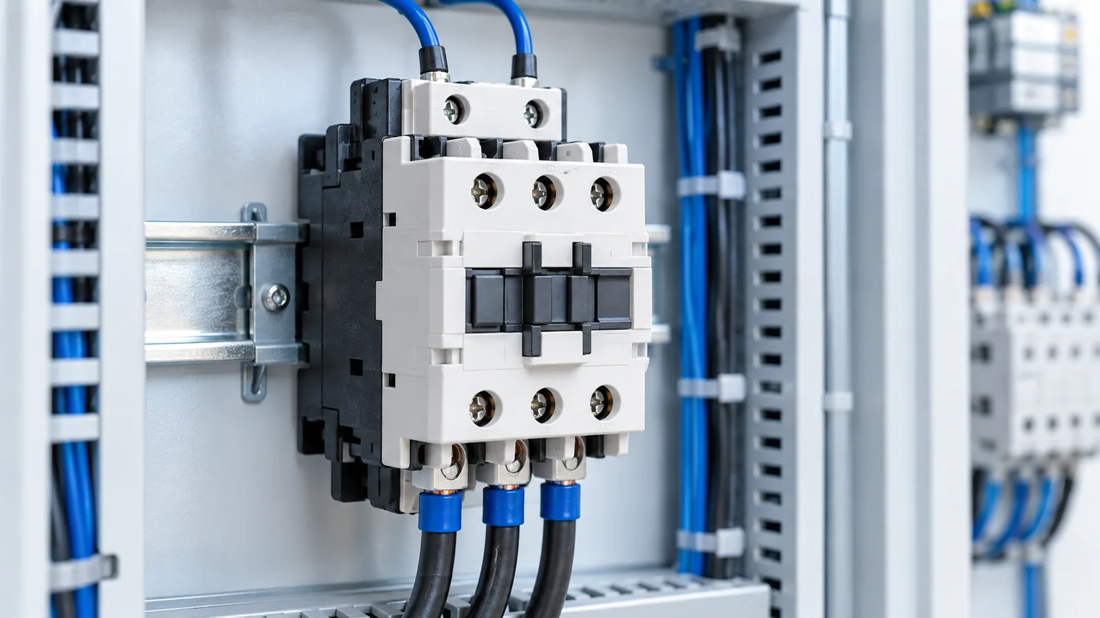
A 60 Hz control supply is a coil-compatibility input, not a complete contactor specification. First confirm the actual voltage and frequency at the coil terminals during pickup and holding. Separately select the main contacts for the load’s operational voltage, current, and switching duty. Finally check overload and short-circuit protection, mechanical fit, and the installation environment. A 50 Hz-only coil should not be assumed suitable at 60 Hz, and a contactor with a suitable coil can still be unsuitable for the load.
This guide addresses electromechanical industrial low-voltage contactors in an IEC-oriented design. IEC 60947-4-1:2023, including its 2026 corrigendum in the IEC catalog, covers electromechanical contactors and motor-starters within its stated voltage scope. It does not turn a generic frequency label into a product-specific operating range. The selected device’s approved technical data and locally adopted rules remain essential.
Specify the control circuit before choosing a coil
Record whether the control source is AC or DC, its nominal voltage, frequency, expected supply variation, and how the voltage reaches the coil. A 60 Hz AC system may use a control transformer, a separate control supply, or an electronic output; the contactor must match the actual coil supply, not merely the plant’s power-system frequency. Check the voltage at the coil under the most demanding credible condition: simultaneous pickup, source variation, control-wire drop, and any series contacts or interlocks.
| Input | What to verify on the candidate contactor | Why it matters |
|---|---|---|
| AC or DC control power | Coil technology explicitly accepted for that supply | An AC coil and DC coil are not interchangeable merely because their nominal volts match. |
| Frequency | 60 Hz is within the declared coil rating or range | A 50/60 Hz marking is evidence only for the marked device. |
| Pickup voltage | Available voltage at the coil during the worst credible energization | A nominal panel voltage can hide transformer sag or wiring drop. |
| Holding voltage and duty | Permitted operating range and continuous duty for the actual coil | Pickup success alone does not prove stable operation. |
| Transient suppression | Accessory compatibility and release-time implications | Suppression devices can affect control behavior and must be checked against the scheme. |
For a transformer-fed circuit, the control-transformer pickup and holding worksheet develops the simultaneous VA cases. Do not substitute the transformer nameplate voltage for a worst-case terminal-voltage check.
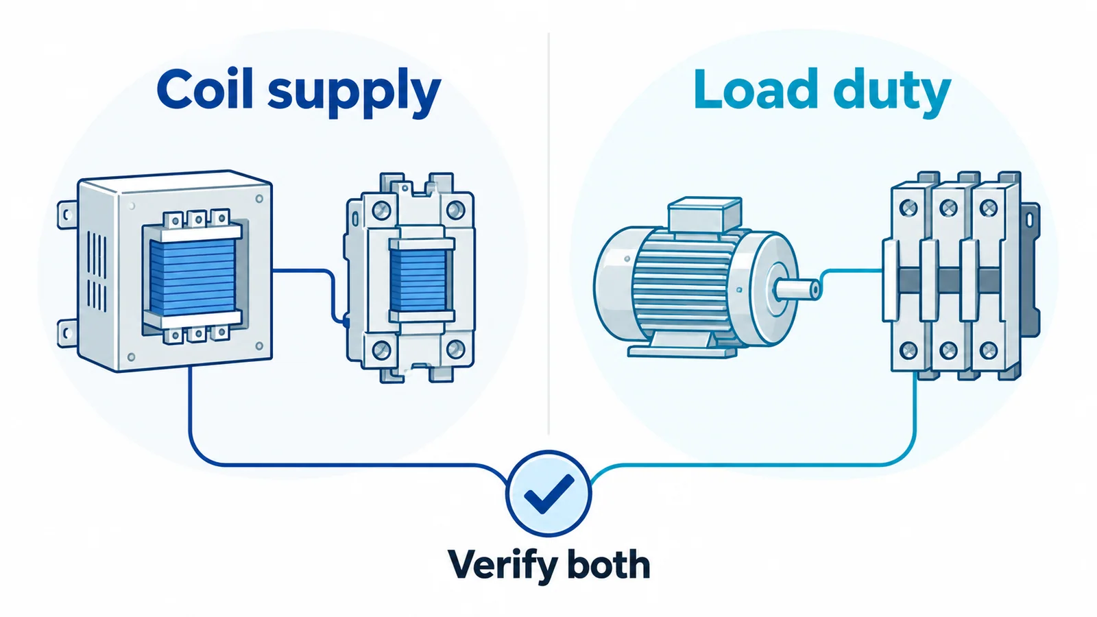
Specify the power contacts for the load, not the coil
State the load type and its real switching sequence. A motor starter, resistive heater, capacitor bank, and lighting circuit do not impose the same make-and-break duty even when their steady current is similar. Use the appropriate utilization category and rated operational current at the actual operational voltage from the device’s declared data. Capture expected starts or operations, reversing or plugging if relevant, and ambient or enclosure conditions that affect permissible use.
The contactor is not automatically the overload or short-circuit protective device. Confirm the associated overload function and the short-circuit protective device (SCPD), including the manufacturer’s tested coordination combination where the design requires one. The breaker-versus-contactor switching-duty comparison explains why a contactor’s repeated switching role does not replace protective interruption.
A practical selection sequence
- Define the two electrical boundaries. Write down control-supply type, voltage, frequency and worst-case terminal voltage; separately record main-circuit voltage, load current and duty.
- Screen the coil. Accept only a coil explicitly rated for the available supply, including 60 Hz where applicable. Verify pickup, holding and release behavior against the actual product data and control scheme.
- Screen the contacts. Match utilization category and operational current at the required voltage. Do not use an unqualified headline ampere figure across different duties.
- Check the starter/protection combination. Verify overload behavior, upstream SCPD, coordination and fault level using the intended combination’s data and the applicable installation rules.
- Check integration. Confirm auxiliary contacts, interlocks, terminal capacity, mounting, enclosure temperature, contamination, and any control-system constraints.
- Record acceptance evidence. Keep the coil designation, frequency/range, utilization-category rating, protection combination and control-voltage assumptions together in the panel schedule.
If the supply is marked only “60 Hz” and the voltage or control topology is unknown, selection is not complete. Likewise, if a candidate has no documented coil operating range, do not infer one from another model or from a generic rule of thumb. Qualified designers should resolve these omissions before procurement or installation.