
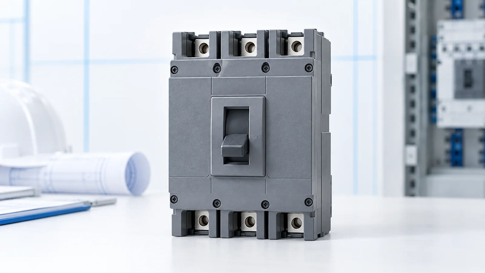
Calculate design current first, but do not choose a breaker from that number alone. For an IEC-oriented low-voltage circuit, the selected device or effective long-time setting must carry the intended load while protecting the actual installed conductors. Its rated voltage and short-circuit breaking capacity must suit the circuit; its trip behavior must also tolerate legitimate starting or inrush without defeating required fault protection. A fixed “load amps → breaker size” chart cannot verify those conditions.
This article is a preliminary selection worksheet for qualified designers, not an installation approval. IEC 60947-2:2024 covers circuit breakers for instructed or skilled persons within its stated voltage scope. IEC 60364-4-43:2023 addresses protection against overcurrent and coordination in low-voltage installations. Locally adopted editions and equipment instructions govern final decisions.
Step 1: calculate the design load current
Use measured or specified current when it represents the operating duty. Otherwise, for a single-phase load with known real input power:
Ib = P / (V × PF)
For a balanced three-phase load:
Ib = P / (√3 × VLL × PF)
Here Ib is design current in amperes, P is electrical input real power in watts, V is single-phase voltage, VLL is line-to-line voltage, and PF is power factor. If the power supplied is mechanical output power, divide by efficiency η as well. These formulas estimate steady current; motor starts, transformer energization, harmonic-rich loads and cyclic duty require separate treatment.
Illustrative arithmetic: a balanced three-phase 12 kW electrical-input load at 400 V line-to-line and PF 0.90 gives Ib = 12,000 / (√3 × 400 × 0.90) ≈ 19.2 A. This is not a recommendation for a 20 A, 25 A or any other breaker. It says nothing yet about corrected cable ampacity, fault level, starting duty or applicable code rules.
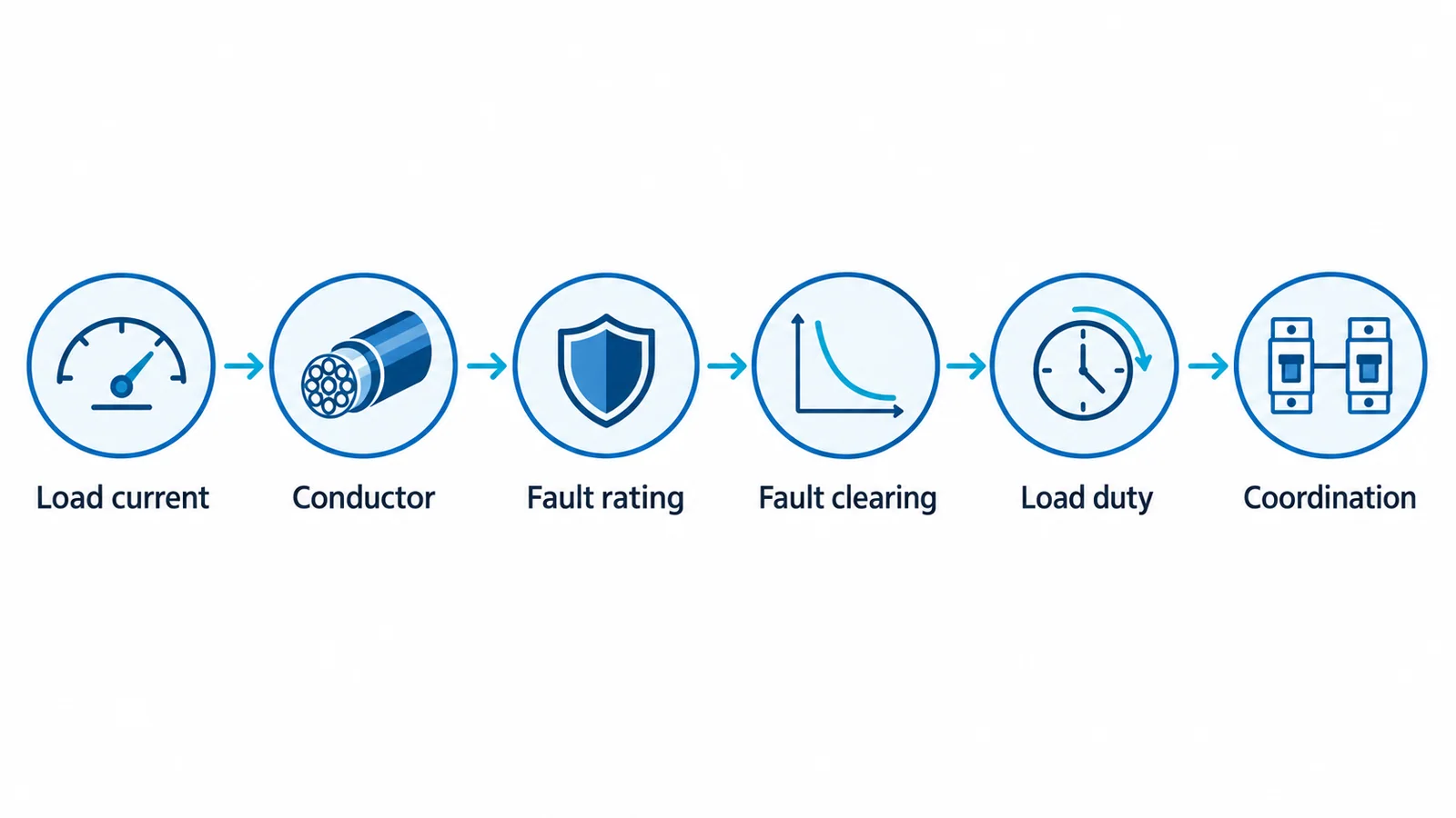
Step 2: apply five selection gates
| Gate | Input needed | Pass condition to document |
|---|---|---|
| Conductor protection | Installed cable size, material, route, ambient, grouping and termination limits | The effective overload setting coordinates with the conductor’s corrected current-carrying capacity under the adopted wiring rules. |
| Fault interruption | Maximum prospective short-circuit current at the breaker location | The device’s applicable breaking rating at the operating voltage and conditions is adequate. |
| Minimum-fault clearing | Minimum expected fault current and earthing arrangement | The intended trip function can disconnect within the locally required conditions. |
| Normal-load behavior | Starting/inrush, duty cycle and thermal environment | Normal operation does not cause unwanted trips; settings are not raised beyond the conductor/protection boundary. |
| System coordination | Upstream and downstream devices; required continuity | Selectivity or backup coordination is verified where the design calls for it, using device-specific curves or tested combinations. |
The cable-first workflow in cable sizing for breaker-protected feeders develops conductor ampacity, voltage drop and thermal withstand in more detail. For a particular nominal rating, the 100 A breaker wire-size discussion shows why the conductor answer depends on the installation rather than the breaker label. Where service continuity matters, use the low-voltage breaker selectivity guide for the separate coordination task.
Why the frame marking is not the final setting
An adjustable molded-case or air circuit breaker can have a frame, sensor or rating plug, and an effective long-time pickup that differ. Record the value that actually governs overload protection rather than substituting the largest printed frame current. Likewise, a household/similar miniature breaker and an industrial breaker may be governed by different product-standard scopes. Do not transfer a B/C/D trip-curve shorthand or a catalogue chart indiscriminately between device families.
The installation’s conductor selection is governed by the applicable wiring rules; IEC 60364-5-52:2009+A1:2024 is the relevant IEC wiring-system reference. Its scope does not make a specific cable or breaker automatically compliant. A qualified designer must document the actual correction factors and device performance data.
Minimum worksheet before approval
Record nominal system voltage and phases; calculated or measured load current; continuous and transient duty; installed cable and corrected ampacity; maximum and minimum prospective fault current; breaker type, rated voltage, breaking rating and effective settings; required disconnection and selectivity; and the locally adopted standard or code. If fault level or cable installation conditions are missing, stop at a provisional load-current estimate, not a breaker size.