
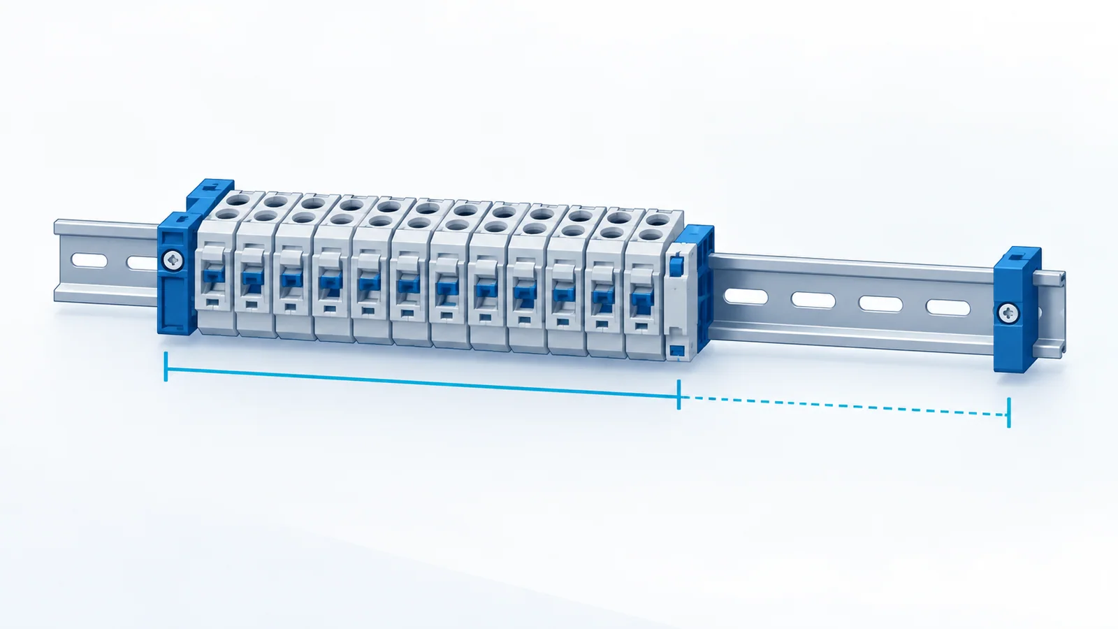
Add the actual widths of every component that occupies the rail, then add a stated layout reserve and compare the result with usable rail length. Terminal count × one nominal pitch is often incomplete: disconnect blocks, protective-earth blocks, end plates, end stops, markers and separators may have different widths. The result is a linear footprint, not proof that wiring bend radius, thermal spacing or panel access is adequate.
For industrial terminal assemblies, IEC 60715:2017 addresses standardized rail dimensions and compatible mounting. IEC 60947-7-1:2025 addresses relevant copper-conductor terminal blocks. Neither catalog page provides a universal width for all blocks or a universal spare-space percentage. Use the selected products’ approved dimensional data and the panel layout rules.
Make a width schedule, not a terminal-count guess
For each distinct component family or function, record quantity nᵢ and occupied width wᵢ in millimetres. Then calculate:
Base occupied length Lbase = Σ(nᵢ × wᵢ) + Σ(accessory widths)
Planned length Lplan = Lbase + explicit spare length
If the project specifies a percentage reserve r, use Lplan = Lbase × (1 + r) and say whether that reserve is applied before or after fixed accessories. Both conventions can be valid if they are documented; mixing them silently causes layout errors. Keep rail cutting tolerances, end clearance, wire access and future expansion separate if the enclosure design requires them.
Worked example with hypothetical dimensions
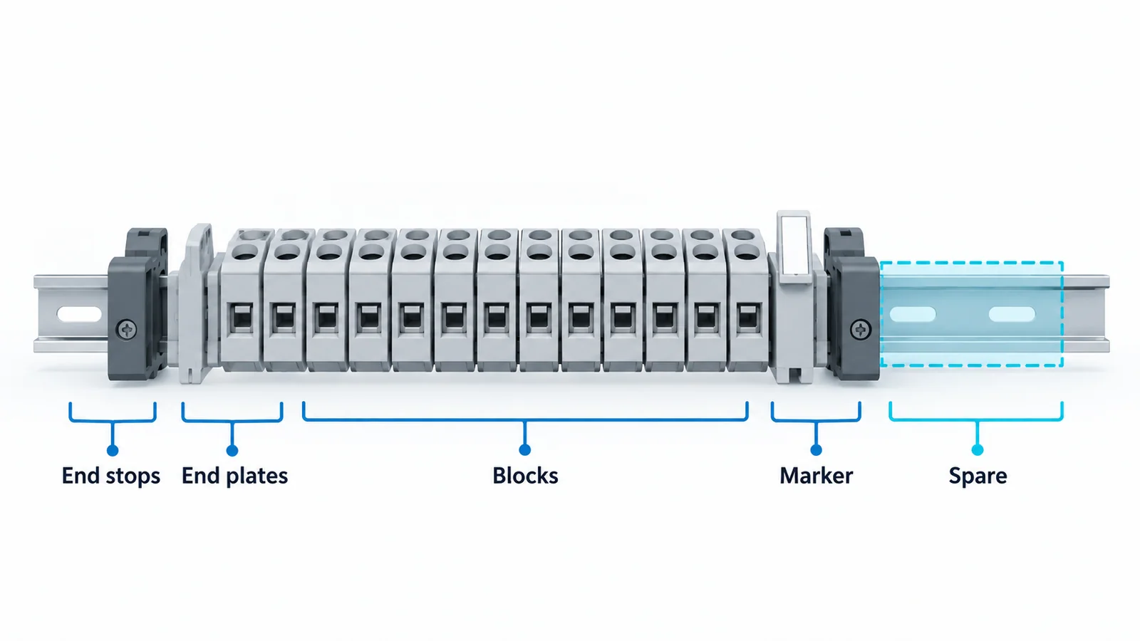
The widths below are assumptions solely for arithmetic, not standardized or manufacturer ratings. Suppose a strip uses 12 feed-through blocks at 6 mm each, two end plates at 2 mm each, two end stops at 9 mm each, and one marker holder at 8 mm:
| Component | Quantity × assumed width | Occupied length |
|---|---|---|
| Feed-through blocks | 12 × 6 mm | 72 mm |
| End plates | 2 × 2 mm | 4 mm |
| End stops | 2 × 9 mm | 18 mm |
| Marker holder | 1 × 8 mm | 8 mm |
| Base | 102 mm |
With an illustrative 15% expansion allowance applied to this base, Lplan = 102 × 1.15 = 117.3 mm. A designer would then compare 117.3 mm with the usable rail span after enclosure mounting obstructions and required end access are accounted for. A nominal 120 mm cut length is not automatically acceptable: small tolerances and access needs may consume the apparent margin. The 15% is not an IEC requirement; choose reserve according to the project’s growth and layout policy.
Four checks after the arithmetic
- Rail and device compatibility: confirm the specified rail profile, material, support and terminal retention—not merely that the block can be pushed onto a rail in a photograph.
- Three-dimensional clearance: inspect depth, height, duct proximity, conductor entry, service access and separation requirements. Width alone cannot prove installability.
- Circuit grouping: retain the intended functional and identification order; separators, disconnect/test units and protective-earth connections may add width or require special placement.
- Revision control: recalculate after any terminal-block substitution or addition. A different product family can change block and accessory widths even if the circuit count is unchanged.
The output is a documented rail-length estimate that can be checked against the actual panel drawing. It is not an installation instruction, a terminal current rating, or a substitute for a qualified panel-layout review. For a separate cost task, see the terminal-block assembly cost guide.