
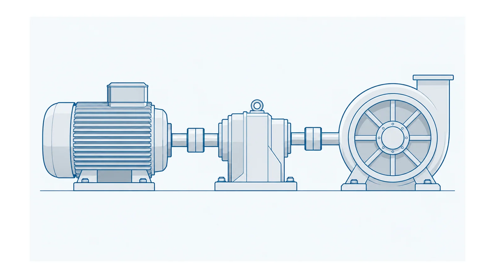
Size the motor from the machine’s required shaft torque and speed over time, then check the variable-frequency drive (VFD) against the motor’s required current and overload duration. Matching two kilowatt labels does not establish that a drive can accelerate a high-inertia load, hold torque at low speed, or absorb repeated deceleration energy.
This guide covers industrial low-voltage three-phase induction-motor drives. Its outcome is a sizing record, not a catalogue recommendation: a continuous and peak motor-shaft duty, the associated thermal constraints, and the evidence needed to accept the converter. Mechanical safety functions, protection settings and commissioning remain separate engineering tasks.
Start with the machine cycle, not the nameplate
Record what the machine must do during starting, running, stopping and dwell. Include abnormal but specified operating conditions, such as a loaded restart; do not silently substitute a lighter normal cycle.
| Machine input | What to record | Why it changes sizing |
|---|---|---|
| Resisting load | Torque versus speed, direction and process condition | A conveyor, fan and winding machine need different shaft envelopes |
| Speed range | Minimum, normal and maximum operating speed | Torque capability and cooling may vary across the range |
| Transmission | Ratio, efficiency and relevant backlash or compliance | Load-side values are not motor-shaft values |
| Inertia | Load, gearbox, coupling and motor contributions | Acceleration torque depends on all inertia referred to one shaft |
| Timing | Acceleration, run, deceleration, dwell and repetitions | A brief demand and a repeated demand have different thermal consequences |
| Environment | Ambient temperature, altitude, enclosure and cooling arrangement | Published equipment ratings have operating conditions |
| Stopping duty | Required stop profile and any overhauling load | The energy path can constrain the converter and braking equipment |
The US Department of Energy’s motor-system sourcebook treats duty cycle as time spent at different loads; a representative maximum value alone misses that operating pattern. DOE motor and drive sourcebook
Keep the arithmetic definitions separate from this selection journey. Use the induction-motor calculation reference when converting torque, power and speed or interpreting motor speed data.
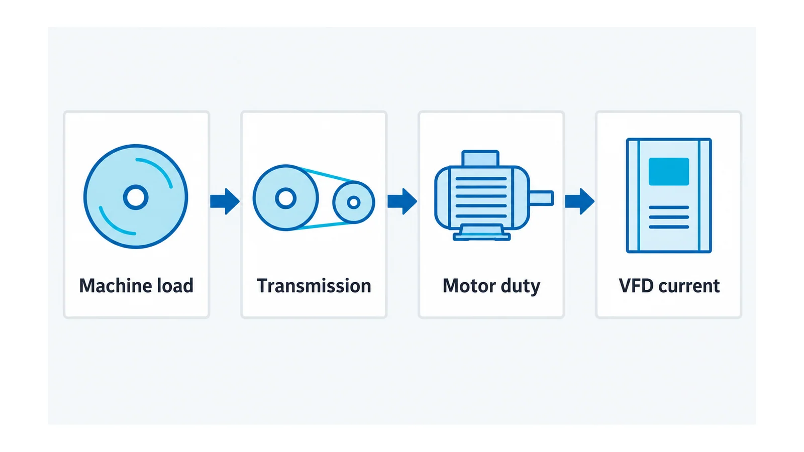
Refer torque and inertia to the motor shaft
For a fixed reduction ratio, define g = motor speed / load speed. With a steady resisting load and transmission efficiency η:
- Motor speed: n_motor = g × n_load.
- Motor load torque: T_motor,load = T_load / (g × η).
- Ideal reflected load inertia: J_reflected = J_load / g².
Add motor and other input-side inertia to the reflected value. Refer every rotating element consistently; a gearbox’s own inertia cannot be omitted simply because its efficiency was included.
For constant equivalent inertia, acceleration torque is T_accel = J_equivalent × α, where α is angular acceleration in rad/s². This is the rotational form of Newton’s second law. The reflected-inertia expression follows from equating kinetic energy at the two shaft speeds. MIT rotational dynamics, MIT rotational-motion materials
These equations assume a rigid, fixed-ratio system. Compliance, varying inertia, friction and process torque can require a more detailed model. Applying efficiency to steady resisting torque is not a substitute for modelling transmission losses during a transient.
Worked example: a geared machine that looks small in kW
Consider a hypothetical machine with the following inputs—not a measured installation:
| Input | Assumed value |
|---|---|
| Load speed and resisting torque | 300 rpm; 400 N·m, constant during acceleration and running |
| Reduction ratio and efficiency | 5:1; 0.90 for the steady resisting-torque calculation |
| Load inertia | 25 kg·m² |
| Motor plus other input-side inertia | 0.20 kg·m² |
| Acceleration | 0 to 1,500 rpm in 3 seconds, constant acceleration |
At the motor shaft:
- Running torque = 400 / (5 × 0.90) = 88.9 N·m.
- Equivalent inertia = 25 / 5² + 0.20 = 1.20 kg·m².
- Final angular speed = 2π × 1,500 / 60 = 157.1 rad/s.
- Acceleration = 157.1 / 3 = 52.36 rad/s².
- Inertial torque = 1.20 × 52.36 = 62.8 N·m.
- Required accelerating torque = 88.9 + 62.8 = 151.7 N·m.
Steady mechanical output at the motor shaft is 88.9 × 157.1 ≈ 14.0 kW. Nevertheless, the model requires approximately 151.7 N·m during the three-second acceleration, before adding omitted mechanical effects or an explicitly justified design allowance. Selecting on 14 kW alone leaves that demand unresolved.
This does not prove that a particular motor or VFD can supply the peak. Required torque must be checked across speed against the motor/converter combination, and the drive’s current capability must support the necessary duration and repetition. Do not infer current directly from this torque number without appropriate motor data.
Make two independent capability checks
Motor: continuous torque, repeated peaks and cooling
Check the entire duty against the motor’s operating envelope, including any constant-power region above base speed. Repeated acceleration or long low-speed operation may be more restrictive than the normal running point.
A shaft-driven fan generally provides less cooling at reduced speed; the DOE sourcebook identifies this as a converter-fed application concern. Resolve it through the declared motor duty, cooling arrangement and thermal evaluation, not an invented universal derating percentage. DOE sourcebook
A root-mean-square (RMS) torque calculation may be a useful screening tool where the model is justified, but it does not automatically cover speed-dependent cooling, magnetic losses or transient thermal limits. Ask for the motor’s capability under the actual cycle.
VFD: output current, overload time and energy path
Check rated output current at the intended operating conditions, then the current-versus-time limit for starting and repeated peaks. State the recurrence and recovery time; a short overload allowance is not permission for unlimited cycling.
Also resolve motor-converter compatibility. IEC TS 60034-25:2022, an International Electrotechnical Commission technical specification, addresses alternating-current (AC) machines used with converters and their interaction; identify the applicable combination rather than assume any inverter and motor form an equivalent system. IEC TS 60034-25 scope
For controls, installation environment and other drive-selection considerations, continue with selecting the proper VFD. Keep circuit protection as a separate coordinated design using the motor-protection circuit-breaker basics.
Do not lose the stopping-energy requirement
The example’s stored rotational energy at full speed is:
E = ½ × J_equivalent × ω² = ½ × 1.20 × 157.1² ≈ 14.8 kJ.
That is an energy inventory, not a brake-resistor rating. Mechanical losses and resisting process torque can absorb part of it; an overhauling load can add energy. The deceleration profile determines power over time. A converter arrangement must either return, dissipate or otherwise handle the energy that actually reaches it, with repetition and thermal recovery included.
A stop demanded by machine safety must not be assumed equivalent to an ordinary controlled deceleration. Have the responsible machine engineer define the required stopping function and its independent verification.
The seven-field release record
Accept the sizing decision only when the file contains:
- The machine torque/speed/time cycle and its worst specified operating condition.
- The transmission ratio, efficiency assumptions and all referred inertias.
- Required motor-shaft continuous and accelerating torque across speed.
- Motor thermal acceptance for repetition, low-speed operation and environment.
- Converter output-current and overload-time acceptance under those same conditions.
- The braking-energy path, stopping profile and repeated-duty capability.
- Open assumptions, evidence owner and a controlled change trigger.
If the machine’s throughput, gearing or stopping time changes, revisit the record. The useful result is not “motor and drive kW match”; it is a traceable capability check for the actual machine cycle.
Sources
- US DOE — Improving Motor and Drive System Performance.
- MIT OpenCourseWare — Rotational dynamics and rotational-motion materials.
- IEC TS 60034-25:2022 — AC machines used in power drive systems, public scope; normative application requirements require the applicable document.